background image

Summary of Contents for HydroSense 153.331492

Page 1: ...ita el manual de instrucciones en espa_ol puede solicitarlo al 1 800 821 2017 NO TRATE DE INSTALAR U OPERAR ESTE CALENTADOR DE AGUA SI NO ENTIENDE LAS INSTRUCCIONES No hacer caso de esta advertencia podria originar lesiones graves o mortales WARNING If the information in these instructions is not followed exactly a fire or explosion may result causing property damage personal injury or death m Do ...

Page 2: ...arm This appliance can cause low level exposure to some of the substances included in the Act IMPORTANT DEFINITIONS Qualified Technician A qualified technician must have ability equivalent to a licensed tradesman in the fields of plumbing air supply venting and gas supply including a thorough understanding of the requirements of the National Fuel Gas Code as it relates to the installation of gas f...

Page 3: ...ssure Use only gas shown on rating plate Maintain required clearances to combustibles Keep ignition sources away from faucets after extended period of non use Read instruction manual before installing using or servicing water heater Explosion Hazard Overheated water can cause watertank explosion Properly sized temperature and pressure relief valve must be installed in opening provided Breathing Ha...

Page 4: ...d Accessibility 13 14 Filling the Water Heater 14 GAS SUPPLY 14 15 Gas Requirements 14 Gas Piping 14 Gas Pressure 15 Gas Pressure Testing 15 COMBUSTION AIR SUPPLY VENTILATION 16 19 Unconfined Space 16 Confined Space 16 All Air from Inside the Building 16 17 All Air from Outdoors 17 Louvers and Grilles 17 Vent Pipe System 18 Draft Hood Installation 18 Vent Pipe Size 18 Vent Connectors 18 19 Chimney...

Page 5: ... VALVE THERMOSTAT 28 29 MAINTENANCE OFYOURWATERHEATER 30 32 Replacement Parts 30 External Inspection Cleaning of theBase Ring Filter 30 Removing theManifold Burner Assembly 30 Removing theBurner fromtheManifold Burner Assembly 30 Replacing thePilot Pilot TubeAssembly 30 31 Cleaning theCombustion Chamber andFlame arrestor 31 Replacing theManifold Burner Assembly 31 32 Piezoelectric Igniter System 3...

Page 6: ...ts it may require preventive maintenance or repair from time to time That s when having a Master Protection Agreement can save you money and aggravation The Master Protection Agreement also helps extend the life of your new product Here s what the Agreement includes Parts and labor needed to help keep products operating properly under normal use not just defects Our coverage goes well beyond the p...

Page 7: ...Protection Association 1 Batterymarch Park Quincy MA 02269 If after reading this manual you have any questions or do not understand any portion of the instructions call the Sears Service Center Carefully plan the place where you are going to put the water heater Correct combustion vent action and vent pipe installation are very important in preventing death from possible carbon monoxide poisoning ...

Page 8: ...G A DIAMETER 22 559 mm OR LESS AND AVAILABLE IN 28 711 mm DIAMETER FOR WATER HEATERS HAVING A DIAMETER 26 660 mm OR LESS BASIC TOOLS You may or may not need all these tools depending on your type of installation These tools can be purchased at your local Sears Store Pipe Wrenches 2 14 356 mm Screwdriver Tin Snips 6 1 82 m Tape or Folding Ruler Garden Hose Drill Pipe Dope or Teflon Tape DRILL SLOT ...

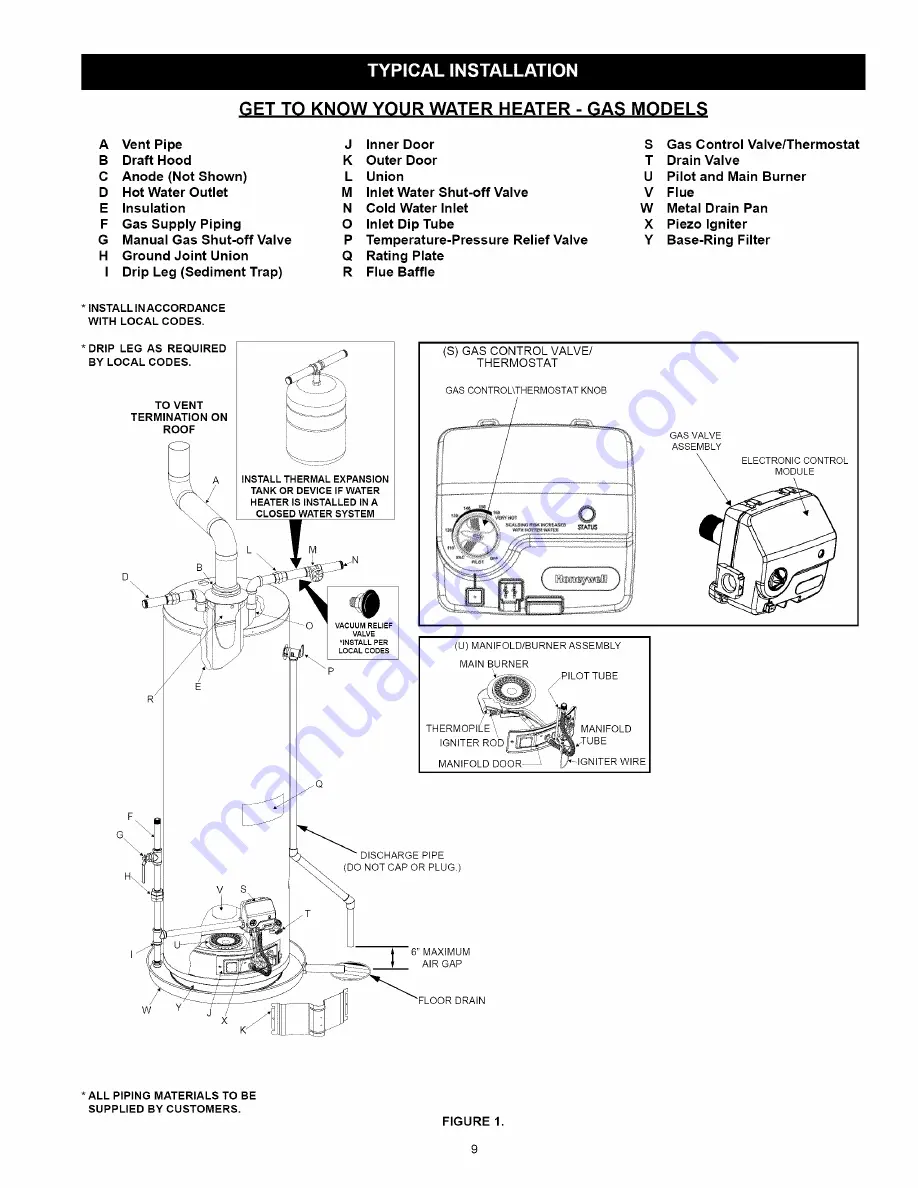
Page 9: ... Thermostat T Drain Valve U Pilot and Main Burner V Flue W Metal Drain Pan X Piezo Igniter Y Base Ring Filter INSTALL INACCORDANCE WITH LOCAL CODES DRIP LEG AS REQUIRED BY LOCAL CODES TO VENT TERMINATION ON ROOF R E F G H v s W j X INSTALL THERMAL EXPANSION TANK OR DEVICE IF WATER HEATER IS INSTALLED IN A CLOSED WATER SYSTEM S GAS CONTROL VALVE THERMOSTAT GAS CONTROL THERMOSTAT KNOB GAS VALVE ASSE...

Page 10: ...eas that contain negative pressure producing devices such as exhaust fans dryers fireplaces etc Is there a furnace air handler in the same room space as the water heater If so has a return air duct system been attached that exits the room If so check for leaks on the air duct system If no air duct system is present correct immediately by contacting a local Heating Ventilation Air Conditioning Refr...

Page 11: ...ately four inches away from where they connect to the water heater See Figure 6 This will avoid cutting off pipes too short Additional cuts can be made later if necessary Disconnect the temperature pressure relief valve drain line When the water heater is drained disconnect the hose from the drain valve Close the drain valve The water heater is now completely disconnected and ready to be removed F...

Page 12: ...be installed indoors and in a vertical position on a level surface DO NOT install in bathrooms bedrooms or any occupied room normally kept closed Locate the water heater as close to the chimney or gas vent as practical Consider the vent system piping and combustion air supply requirements when selecting the water heater location The venting system must be able to run from the water heater to termi...

Page 13: ...while at the same time shutting off its water supply Insulation Blankets Insulation blankets available to the general public for external use on gas water heaters are not necessary with Kenmore products The purpose of an insulation blanket is to reduce the standby heat toss encountered with storage tank heaters Your Kenmore water heater meets or exceeds the National Appliance Energy Conservation A...

Page 14: ...located near the gas control valve thermostat If the information does not agree with the type of gas available do not install or light Call your dealer NOTE An odorant is added by the gas supplier to the gas used by this water heater This odorant may fade over an extended period of time Do not depend upon this odorant as an indication of leaking gas Gas Piping The gas piping must be installed acco...

Page 15: ...ce of ignition If the fuel is spilled while purging the piping system of air follow the WHAT TO DO IF YOU SMELL GAS instructions on the cover of this manual IMPORTANT The gas supply pressure must not exceed the maximum supply pressure as stated on the water heater s rating plate The minimum supply pressure is for the purpose of input adjustment Table 1 Natural Gas Pipe Capacity Table Cu Ft Hr Capa...

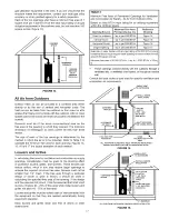
Page 16: ...for various BTUH inputs TABLE 2 Minimum Square Typical Room BTUH Input Feet with with 8 Ceiling 8 Ceiling 30 000 188 9 x 21 45 000 281 14 x 20 60 000 375 15 x 25 75 000 469 15 x 31 90 000 563 20 x 28 105 000 657 20 x 33 TABLE 2 Minimum Square Typical Room Feet with 8 BTUH Input 8 Ceiling with Ceiling 120 000 750 25 x 30 135 000 844 28 x 30 IMPORTANT The area must be open and be able to provide the...

Page 17: ...n it should be used in calculating the specified free area of the opening If the design and free area are not known it can be assumed that most wood louvers will allow 20 25 of free area while metal louvers and grilles will allow 60 75 of free area Louvers and grilles must be locked open or interconnected with the equipment so that they are opened automatically during equipment operation Keep louv...

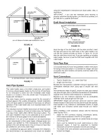
Page 18: ...llation ETAL SCREWS FOUR PROVIDED _ _k P DRAFT HOOD SLOTJ _JACKET TOP p LSLOT INSTALL THE DRAFT HOOD WITH THE FOUR SCREWS PROVIDED FIGURE 18 Align the legs of the draft hood with the slots provided Insert the legs and secure the draft hood to the water heater s top with the four screws provided as shown in Figure 18 Do not alter the draft hood in any way If you are replacing an existing water heat...

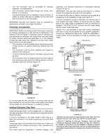
Page 19: ...raft hood by a listed vent connector or by directly originating at the draft hood opening Vertical gas vents must terminate with a listed cap or other roof assembly and be installed according to their manufacturer s instructions Gas vents must be supported to prevent damage joint separation and maintain clearances to combustible materials Figures 20 and 21 IMPORTANT This gas vent must be terminate...

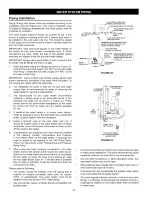
Page 20: ...sure relief valve must be installed in the opening marked Temperature and Pressure T P Relief Valve on the water heater A discharge line must be added to the opening of the T P Relief Valve Follow the instructions under Temperature and Pressure Relief Valve After piping has been properly connected to the water heater remove the aerator at the nearest hot water faucet Open the hot water faucet and ...

Page 21: ...ge quantities in the event of excessive temperature or pressure developing in the water heater The valve s relief pressure must not exceed the working pressure of the water heater as stated on the rating plate IMPORTANT Only a new temperature and pressure relief valve should be used with your water heater Do not use an old or existing valve as it may be damaged or not adequate for the working pres...

Page 22: ... unit It must be replaced Pl_ tGNITOR STATUS _ LED GAS CONTROL _GAS CONTROL FIGURE IA FIGURE B FIGURE C MAIN BURNER KNOB _ _ to_ _ PILOT OFF POSITION PILOT POSITION ON POSITION CONTROL KNOB FIGURE D 1 2 3 4 5 6 7 8 STOP Read the safety information above on this label Turn gas control knob fully counterclockwise to OFF SEE FIGURE A Remove the outer burner door located below the gas control Wait fiv...

Page 23: ...y vary up to 30 F 16 7 C higher or lower at the point of use such as bathtubs showers sink etc HOTTER WATER CAN SCALD Water heaters are intended to produce hot water Water heated to a temperature which wilt satisfy space heating clothes washing dish washing and other sanitizing needs can scald and permanently injure you upon contact Some people are more likely to be permanently injured by hot wate...

Page 24: ...used a lower thermostat setting wilt reduce energy losses and may satisfy your normal hot water needs If hot water use is expected to be more than normal a higher thermostat setting may be required to meet the increased demand When leaving your home for extended periods vacations etc turn the temperature dial to its lowest setting This wilt maintain the water at tow temperatures with minimum energ...

Page 25: ... typical compounds which are potentially corrosive If when inspecting the vent system you find sooting or deterioration something is wrong Call the local gas supplier to correct the problem and clean or replace the flue and venting before resuming operation of the water heater Burner Inspection Flood damage to a water heater may not be readily visible or immediately detectable However over a perio...

Page 26: ...nds on water conductivity not necessarily water condition A corroded or pitted anode rod indicates high water conductivity and should be checked and or replaced more often than an anode rod that appears to be intact Replacement of a depleted anode rod can extend the life of your water heater Inspection should be conducted by calling the Sears Service Center for an authorized contractor At a minimu...

Page 27: ... flow is directed away from people 6 Open the water heater drain valve and allow all the water to drain from the tank Flush the tank with water as needed to remove sediment 7 Close the drain valve refill the tank and restart the heater as directed under the Operating Your Water Heater section If the water heater is going to be shut down for an extended period the drain valve should be left open IM...

Page 28: ...in the tank and contact a qualified service technician Refer to the Draining and Flushing section D Installing a Gas Control Valve Thermostat Full Assembly NOTE If the electronic control module gas valve and backptate are not assembled assemble them before proceeding 1 If it is not needed remove the metal gas valve nipple from the gas control valve thermostat It is screwed onto the threaded plasti...

Page 29: ...ULE O THERMOPILE TORX SCREW LOCKING TAB TANK SENSOR GAS VALVE ASSEMBLY GAS VALVE NIPPLE GAS VALVE ASSEMBLY FRONT VIEW WITH ELECTRONIC CONTROL MODULE REMOVED INLET GAS SUPPLY LOCKING LOCKING TAB TORX PILOT BURNER TAB SCREW TUBE TUBE FIGURE 31 29 ...

Page 30: ...de the water heater Figure 11 Note the position of the shut off valve in the open on position then proceed to turn it off 2 Turn the temperature dial to the OFF position ELECTRONIC CONTROL MODULE IGNITER _ TANK SENSOR THERMOPiLE _ PLUG PILOT MANIFOLD TUBE TUBE FIGURE 32 3 Remove the outer door 4 Remove the two screws securing the manifold door assembly to the combustion chamber Figure 33 GAS CONTR...

Page 31: ... located in the middle opening and thermopile wires in the bottom opening 12 Reposition the two piece wire connector in the manifold door opening and secure it with the retainer clip 13 Before you proceed to the next step install the new brass ferrule nut in the gas control valve thermostat s pilot tube opening HAND TIGHTEN ONLY 14 See Replacing the Manifold Burner Assembly Thermopile Connector Wi...

Page 32: ...piece wire connector manifold tube and pilot tube connections for leaks Check for leaks by brushing on an approved noncorrosive leak detection solution Bubbles forming indicate a leak Correct any leak found IMPORTANT All leaks must be fixed immediately 11 Replace the outer door MANIFOLD TUBE CLOSE UP INSIDE VIEW OF THE COMBUSTION CHAMBER __ SLOT TIP BRACKET FIGURE 39 Piezoelectric Igniter System T...

Page 33: ...ABLE 5 Expansion Tank Sizing Chart Expansion Tank Capacity Needed Inlet Water Pressure 40psi 50psi 60psi 70psi 80psi Water Heater Capacity Gallons 30 40 50 66 82 2 2 2 5 5 2 2 2 5 5 2 2 5 5 5 2 2 5 5 5 2 5 5 5 5 Highest recorded inlet water pressure in a 24 hour period or regulated water pressure NOTE Expansion tanks are pre charged with a 40 psi air charge If the inlet water pressure is higher th...

Page 34: ... the water heater is leaking until there has been enough time for the water in the tank to warm up An undersized water heater will cause more condensation The water heater must be sized properly to meet the family s demands for hot water including dishwashers washing machines and shower heads Explosion Hazard Flammable hydrogen gases may be present Keep all ignition sources away from faucet when t...

Page 35: ...lt in death or serious injury Instruction Manual must remain with water heater Read this manual first Then before checking the water heater make sure the gas supply has been turned OFF and never turn the gas ON before the tank is completely full of water Never use this water heater unless it is completely filled with water To prevent damage to the tank the tank must be filled with water Water must...

Page 36: ... pilot off Replace gas control valve thermostat 8 flashes and burner off 6 second solid light Pilot stays tit only when control knob Overheat failure Replace gas control valve followed by 4 flashes is depressed in PILOT position thermostat 6 second solid light Pilot stays tit onlywhen control knob Electronic control module failure Replace followed by 7 flashes is depressed in PILOT position module...

Page 37: ...ermostat 11 Clean locate source and correct 12 Replace thermopite 13 See maintenance section for inspection and cleaning of flame arrester 14 Replace water heater eliminate flammable SLOW HOT WATER RECOVERY DRIP FROM RELIEF VALVE 15 function actuated Base ring filter obstructed 1 Thermostat set too high 2 Sediment or time in tank 3 Water heater too small for job 4 Wrong piping connections 5 Leakin...

Page 38: ......

Page 39: ......

Page 40: ......

Page 41: ......

Page 42: ......

Page 43: ......

Page 44: ......

Reviews: