Man-1078_Sigma_CP_22
Page 14 of 24
For panels with software version Sigma242.hex or below, the Enable controls keyswitch and Write Enable
switch must both be set to off.
13B
14. Connection to Ancillary boards
Ancillary boards connect via a 2 core cable to the terminals marked RS485 + and – on the Sigma CP main
control panel PCB. Up to 7 Ancillary boards may be connected and each board has terminals for the
incoming cables and outgoing cables. All except the last ancillary board, sounder board or repeater panel
connected to the cable must have the jumper links J2 removed.
Set the ancillary board address using the DIP switch (SW2); ensure no two ancillary boards share the same
address.
Apply power to main panel and all ancillary boards then turn on the enable keyswitch and set the write
enable slide switch to on, briefly press the PROCESSOR RESET button on the main panel, wait for a few
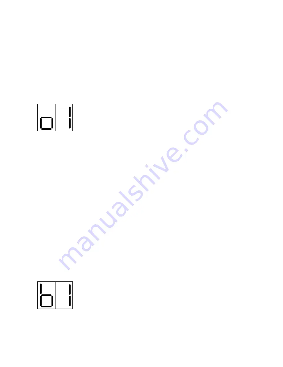
seconds and the main panel will show the addresses of the ancillary boards that were found on the display
for instance o1 indicates that an ancillary board at address 1 has been found.
Press the ENTER button to accept each ancillary board that has been found.
The control panel will report a fault if any ancillary boards that have been accepted
become faulty or go off line.
For full details of commissioning procedures for ancillary boards see the Sigma CP Ancillary board Operation
and maintenance manual.
Please note that Ancillary boards can only be fitted to panels containing boards
labelled S4XXA or above. They will not work with panels containing boards without
an alpha suffix.
14B
15. Connection to 8 way Sounder boards
Sounder boards connect via a 2 core cable to the terminals marked RS485 + and – on the Sigma CP main
control panel PCB. Up to 7 Sounder boards may be connected and each board has terminals for the
incoming cables and outgoing cables. All except the last Ancillary board, Sounder board or Repeater
connected to the cable must have the jumper links J2 removed. Sounder boards must be powered from a
separate power supply which is suitably rated to supply the full sounder load that is connected. This can be
up to 4 Amps if all circuits are fully loaded.
Set the Sounder board address using the DIP switch (SW2); ensure no two Sounder boards share the same
address.
Apply power to main panel and all Sounder boards then turn on the enable keyswitch and set the write
enable slide switch to on, briefly press the PROCESSOR RESET button on the main panel, wait for a few
seconds and the main panel will show the addresses of the sounder boards that were found on the display
for instance
b1 indicates that a sounder board at address 1 has been found.
Press the ENTER button to accept each Sounder board that has been found.
The control panel will report a sounder fault if any Sounder boards that have been
accepted become faulty, have cable faults on their outputs or go off line.
For full details of commissioning procedures for Sounder boards see the Sigma CP Sounder board Operation
and maintenance manual.
Please note that Sounder boards can only be fitted to panels containing software
SIGMA242.HEX or later.
Summary of Contents for Sigma CP K Series
Page 1: ......


