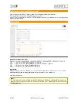
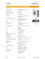
background image

MultiSensor-LAN

In contrast to the MultiSensor-RF with Funk interface can the MultiSensor-LAN also use in stand alone 
operation without an AlarmManager. For configuration in stand alone operation a web server is integrated, 
which allows you to configure the device via LAN and a web browser.

Over the SNMP interface, an integration in network management systems is possible.
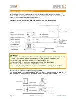
Connection via PC:

!

Connect the LAN jack from the MultiSensor-LAN over a LAN cable with your network 

!

!

!

and your PC. Pay attention that you have to use a Cross-Over network cable, by a 

!

!

!

direct connection. Set the IP address of your PC to for example „192.168.100.123“.

Default settings

Voltage supply:

!!

PoE (Power over Ethernet). The change to external power supply is possible.

Default IP-address: 

!

192.168.100.223 

(older software versions 192.168.100.222)

Subnet mask:

! !

255.255.255.0

Gateway:

!

!

0.0.0.0

User:

! !

!

admin

Password:

!

!

password

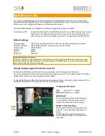
Change voltage supply from PoE to external

By default, the MultiSensor-LAN is set to the power supply over PoE (power over ethernet).
So, you can operate the device without another power supply direct by an PoE capable switch.The market 
standard PoE injectors can also be used for power supply.

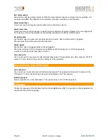
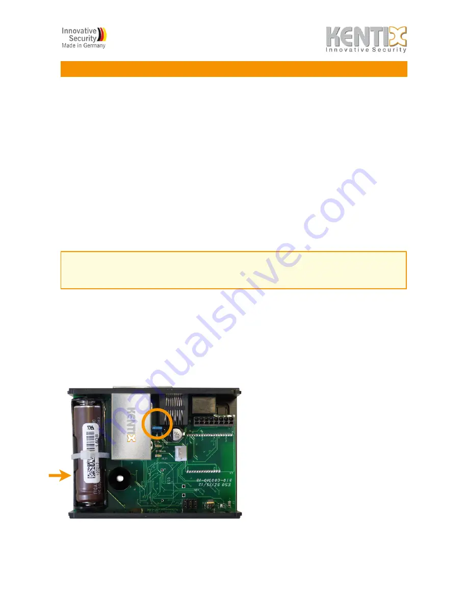
To operate MultiSensor-LAN over an external power supply, you have to change a jumper (Jumper JP1) on 
the platine. Pay attention to the picture below, for switching the jumper.

Changing power supply:

PoE:

        Jumper to 1 + 2 (POE)

External: 

Jumper to 2 + 3 (EXT)

IMPORTANT!

Do not change the jumper while the device 
is under tension. Disconnect the device 
always from network and power supply.

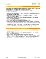
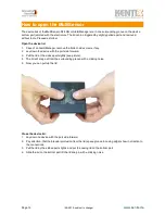
RESET to default settings:

Briefly press the button on the bottom side 
with a flat, non-conducting object made of 
plastic.
Restart after 30 seconds the device and 
use the default settings for IP address and 
user login.

Important! Reset the IP address

If you have forgotten the login informations of the MultiSensor-LAN, activate the RESET button at the device inside. 
The device will reset the login information to the default settings. The RESET button is on the bottom side, after you 
have remove the device-lid (see picture below).

Page 4                                          

!

(09-2012, subject to change)

!

www.kentix.de

RESET

Summary of Contents for MultiSensor-LAN

Page 1: ...User Manual MultiSensor LAN From Firmware Version 2 xx xx...

Page 2: ...ation Network 6 2 6 Configuration Sensors and Alarm 7 2 7 User accounts and notification 8 2 8 Language 8 2 9 Software update MultiSensor LAN 9 2 10 Copy or save Configuration of MultiSensor LAN 9 2 1...

Page 3: ...actices Energy and water utility Safety note The installation of the MultiSensors must be run by an competent person In a power failure the settings are not lost Energized relays drop out and go back...

Page 4: ...t to the power supply over PoE power over ethernet So you can operate the device without another power supply direct by an PoE capable switch The market standard PoE injectors can also be used for pow...

Page 5: ...hot or exceeded NOK There is a measurement undershot or exceeded an alarm is triggered ON Function or input output status is switched on OFF Function or input output status is switched off Monitoring...

Page 6: ...larmManager and set the hook FTP server activation The integrated FTP server can be activated or deactivated The FTP access will be needed for a software update of the device Look up in the chapter so...

Page 7: ...he CO content The measurement is construed to the highest sensitivity and can be changed slightly in the adjustment Carbon Monoxide concentrations like they emerge in fires are detected even at 100 se...

Page 8: ...me when a triggered alarm shall be triggered The alarm will be sent to the entered e mail addresses until all values are in normal range again A value of 0 sets the alarm repeating to inactive User ac...

Page 9: ...ate file will be deleted from the filesystem of the MultiSensor IMPORTANT During the update procedure the power supply must not break 7 Now the MultiSensor is accessible and you can see the software v...

Page 10: ...minutes Current data http MultiSensorIP xml values xml Historical data http MultiSensorIP xml record xml Switch alarm output 2 In the category system you can find a way to turn on the alarm output 2...

Page 11: ...nsor there where is also the config ini file After a reboot the configured command sequence will send to the camera in case of an alarm Up to five cameras can be controlled create for each camera a ne...

Page 12: ...The alarm inputs of the device are only on System connector 1 of the terminal connection of the KIO1 adapter available Page 12 09 2012 subject to change www kentix de IMPORTANT The switching outputs 6...

Page 13: ...port side forward 3 Pull the lid at the sides apart sightly see picture 4 The lid will snap out from the surrounding groove with a clicking noise 5 Now you can pull up the lid Close the device lid 1 L...

Page 14: ...RM red RUN yellow LINK ACT at the LAN jack LAN 10 100 Mbit LAN connection integrated web server SNMP Simple Network Management Protocol SNMP V2 write read SNMP Traps XML Output Actual and historical v...

Page 15: ...facturers websites Copyright Notice All rights reserved Any text images graphics animations and videos as well as content and structure of this manual are protected by copyright and other laws protect...

Reviews: