background image

T

K

M

O

Q

S

L

N

P

R

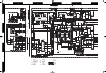
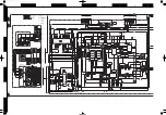
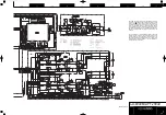
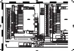
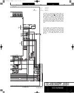
CD-4900M/DPF-J9030

Y32-8250-10

81

82

83

84

85

86

87

88

89

90

91

92

93

94

95

96

97

98

99

100

50

49

48

47

46

45

44

43

42

41

40

39

38

37

36

35

34

33

32

31

A5

A4

A3

D0

D1

D2

D3

D4

D5

D6

D7

A10

A15

A13

A8

A9

A1

1

A0

A1

VSS

SBUSY

S

D

ATA

SYSM

IC-RESET

STB2

MUTEG

SCOR

RESET

XT1

XT2

VSS

X1

X2

VDD

D

ATA

XLA

T

CLOCK

SENS

SCLK

MON

80

79

78

77

76

75

74

73

72

71

70

69

68

67

66

65

64

63

62

61

60

59

58

57

56

55

54

53

52

51

1

2

3

4

5

6

7

8

9

10

11

12

13

14

15

16

17

18

19

20

21

22

23

24

25

26

27

28

29

30

A6

A7

A12

A14

A16

SQCK/SCK

SO

SQSI

SI

STB1

LDC

TXD-SUB

RXD-SUB

SQCK/SCK-SW

TXD-R

RXD-R

AVREF1

LOADM+2

LOADM-2

AVSS

DISC-SW2

LOAD-SW2

UNLOAD-SW2

DOOR-SW

JOG1

JOG2

8/16

A/DO

AVREFO

AVDD

A2

NC

S3-SW

S2-SW

RD(OE)

WR(WE)

S1-SW

ASTB(CS)

VDD

+5VPUL

RTRN

RWR

RWRR

L-D7

L-D6

L-D5

L-D4

L-D3

L-D2

L-D1

L-D0

TEST

DISC-SW

ROTLYM-

LOADM+1

LOADM-1

LOAD-SW1

UNLOAD-SW1

CS

20

R38

1M

R27

C19

C20

7P

7P

100u6.3

C18

+

81

82

83

84

85

86

87

88

89

90

91

92

93

94

95

96

97

80

79

78

77

76

75

74

72

73

70

71

11

10

9

8

7

5

6

4

13

14

12

VCC

3

2

1

56

57

55

54

49

50

45

48

44

34

36

35

32

31

33

R103 10K

R143 47K

X2

12.5MHz

C59

0.01

C25

330u6.3

+

330u6.3

C26

+

0.01

C66

2

3

4

5

6

10

23

24

26

25

29

28

27

7

R140 47K

R141 47K

47K

R96 10K

R97 10K

R98 10K

R99 10K

4.7K

71

57

56

55

75

74

72

C28

R40 13K

C30

R42 15K

R44 10K

150P

R43

C27

R39

R41

C29

150P

15K

13K

10K

820P

47u10

C67

+

47u10

C58

+

+

C56

100u10

C55

1u50

+

R91

4.7K

R92

2.2

C57 1F5.5

R93

+

+5V

+7.5V

VDD

VDD

+5V

+7.5V

+5V

820P

X1

16.9344

MHz

GND

INPUT

ONLY

N-CH

+5V

+5V

VDD

VDD

VDD

+5V

+5V

VDD

+5V

+5V

+5V

+5V

+5V

+7.5V

+5V

+5V

+5V

+5V

+5V

+5V

+5V

+5V

+5V

+7.5V

+7.5V

+7.5V

R102

47K

14 13

12 11

10 9

8

7

6

5

4

3

2

1

Lch

AGND

Rch

+5V

+7.5V

uGND

u+5V

RMUTE1

S

D

ATA

SBUSY

8/16

RXD-R

TXD-R

DOUT

1

2

3

4

5

6

7

8

9 10 11 12

+5V

uGND

+7.5V

GND

+5V

RST

LOD-S2

UNLDS2

LODM-2

LODM+2

RXD-S

TXD-S

5

4

3

2

1

GND

+7.5V

-40V

F

F

1

2

3

4

5

6

7

8

9

10

11

12

13

14

15

16

17

STB1

LCD

DOOR-SW

JOG1

JOG2

SCK

SO

SI

RST

STB2

F

F

-40V

+7.5V

GND

GND

+5V

65

66

68

69

R106

58

R107

59

4.7K

4.7K

45

54

49

65

50

66

58

59

62

63

68

69

+7.5V

+7.5V

+7.5V

+7.5V

+7.5V

+7.5V

40V

40V

46

R100

4.7K

R101

28

27

26

25

24

23

22

21

20

19

18

17

16

15

GND

GND

GND

GND

GND

GND

D7

D6

D5

D4

D3

D2

D1

D0

1

2

3

4

5

6

7

8

9

10

11

12

13

14

RWRR

RWR

RTRN

GND

GND

REM

VDD

XO

XI

GND

RST

WDOUT

17

18

19

20

21

22

23

24

25

26

27

28

29

30

31

32

D3

D4

D5

D6

D7

CSRAM

A10

RD

A1

1

A9

A8

A13

WR

CS

A15

VCC

16

15

14

13

12

11

10

9

8

7

6

5

4

3

2

1

GND

D2

D1

D0

A0

A1

A2

A3

A4

A5

A6

A7

A12

A14

A16

NC

86

83

82

81

80

79

78

77

76

85

84

87

88

89

90

91

92

5

97

96

95

94

6

93

R142

13

12

11

11

12

13

X3

3.64MHz

0.1

C99

47u6.3

C68

+

63

62

22u16

C102

+

22u16

C101

+

46

Q26

270

R205

1K

100P

C157

47K

R108

+5V

+5V

+5V

+5V

+5V

+5V

+5V

+5V

+5V

+5V

+5V

+5V

+5V

+5V

+5V

+5V

+5V

+5V

+5V

+5V

+5V

+5V

(BOTTOM VIEW)

D4

D5

D3

D2

-OVER)

LOGIC IC

(SQCK CHANGE

S RAM

(CD TEXT DATA)

(S-RAM)

D30

Q26

D31

D32

u-COM

+5V AVR

CN13

CN15

CN11

CN6

(BOTTOM VIEW)

Q24

Q23

(BOTTOM VIEW)

D

C

B

-CN14

X32-B/8

2/3

3/3

X32-C/8
-CN7

-CN12

X32-F/8

2/3

2/3

X25-
CN4

LCD COMMUNICATION
u-COM

S-RAM CS

BUFFER

CONTROL

(INTERLOCUTOR REMCON)

(BOTTOM VIEW)

IC8

IC11

(X32-3502-74) (A/8)

IC10

IC9

D

A

B

C

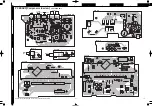
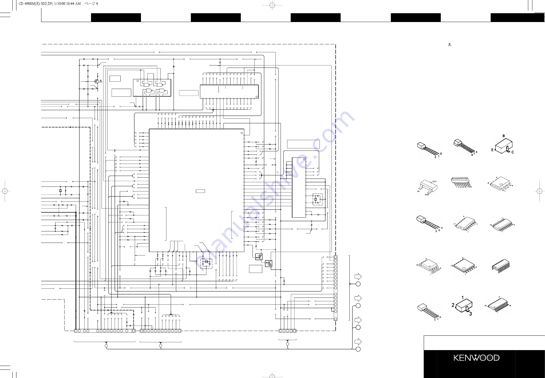
CD-4900M(K) (1/3)
DPF-J9030(T,E) (1/3)

4.8V

4.9V

0.3V

5.0V

4.9V

7.5V

0.2V

5.0V

5.0V

5.0V

5.0V

SL16:5.0V

XS8:0V

4.6V

4.8V

5.0V

5.0V

5.0V

5.0V

5.0V

0V

0V

2.5V

2.7V

0V

0V

0V

0V

0V

0V

5.0V

0V

5.0V

0.2V

0.2V

5.0V

5.0V

0.2V

5.0V

5.6V

4.9V

4.9V

5.0V

0V

5.0V

5.0V

5.0V

5.0V

0V

0V

0V

5.0V

4.6V

5.0V

0V

0V

5.0V

CAUTION: For continued safety, replace safety critical com-
ponents only with manufacturer's recommended parts (refer
to parts list). 

indicates safety critical components. For

continued protection against risk of fire, replace only with
same type and rating fuse(s). To reduce the risk of electric
shock, leakage-current or resistance measurements shall
be carried out (exposed parts are acceptably insulated from
the supply circuit) before the appliance is returned to the
customer.

The  DC voltage is an actual reading measured with a high
impedance type voltmeter. The measurement value may
vary depending on the measuring instruments used or on
the product. Refer to the voltage during PLAY unless other-
wise specified; The value shown in (

) is the voltage mea-

sured at the moment of STOP.

2SA954
2SC2003
2SC3246
2SC3940A

DTA113ZSA
DTC124ESA
2SC2458

2SA1576A
2SA1586

UN4212
UN4219
2SC3311A

DTA124EUA
DTC124EUA

TA8409S

NJM2115M

UN5212

2SK246

TC74HC00AF

CXA1571M

5M51008BFP70LL

NJM2100M

LB1930M

BA5979S

16   

17   

32   

1   

Summary of Contents for CD-4900M

Page 1: ... jack E63 0120 05 Miniature phone jack E11 0360 05 Power cord bushing J42 0083 05 Miniature phone jack E11 0293 05 AC power cord E30 Refer to parts list on page 26 In compliance with Federal Regulations following are repro ductions of labels on or inside the product relating to laser product safety Please refer to the service manual CD 223M DPF J3010 CD 224M DPF J5010 B51 5409 00 if need more info...

Page 2: ...type user file and best selection can be reset by the following procedure Operation to reset The microcomputer may malfunction impossibility to operate erroneous display etc when the connection cords are un plugged while power is ON or due to an external factor In this case execute the following method to reset the microcomputer and return it to normal condition Unplug the power cord from the powe...

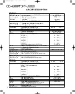
Page 3: ...DM 2 62 LOADM 2 7P LOAD SW2 58 UNLOAD SW2 4P 5P 6P UNLOAD SW2 59 DLE SW2 uPD784217GF502 ON LED A LED B STANDBY X32 IC15 uPD780204 CLK RESET 43 RESET INPUT DOT DRIVER SI IC RESET 47 PERIPHERY IC RESET STB 46 STB2 JOG 55 JOG 2 X32 IC10 56 JOG 1 14 21 D0 D7 LASER ON OFF 70 LDC D7 D0 uPD17215GT 737 ANALOG MUTE 48 SYSM SPINDLE MOTOR ON OFF 31 MON RWRREQ 13 RWRREQ RTREN 11 RTREN 8 16BIT 54 8 16 RWR 12 R...

Page 4: ...kup 27 LOADM 1 O Loading motor for main pickup 28 LOAD SW1 I Loading switch for main pickup 29 UNLOAD SW1 I Unloading switch for main pickup 30 CS O Chip selector 31 MON O Control port of poor focus works 32 SCLK O Sens serial data read clock 33 SENS I SENS signal input 34 CLOCK O Serial data clock 35 XLAT O CXD2587Q latch H î L latch 36 DATA O Serial data output 37 VDD Power supply 5V 38 39 X1 2 ...

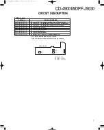
Page 5: ... O SQCK SCK DOT DSP clock selector L DSP 68 RXD1 I UART communication input from sub u com 69 TXD1 O UART communication output to sub u com 70 LDC O Laser on off L Laser diode on 71 STB1 O Strobe signal output to dot driver 72 SI I Data input from dot driver 73 SQS1 I Sub code read data input 74 SO O Data output to dot driver 75 SCK SQCK O Dot driver sub code read clock 76 83 A16 14 12 7 3 O Addre...

Page 6: ...nd 41 in the order And release the test mode CONFIRM Release the test mode TIMER PLAY SW Check the switch position TIMER ON TIMER OFF OPERATION A B Change the mechanism A and B Insert the AC plug to CHECK THE MECHANISM JAMMING the wall outlet with Clamp the Disc No1 2 100 50 200 and 199 in the order pressing the UP key Insert the AC plug to THE MECHANISM TEST MODE the wall outlet with Display show...

Page 7: ...ut of S1 The turning direction error to clockwise MECHA ERROR 04 No input of main load sw MECHA ERROR 05 No input of main unload sw MECHA ERROR 06 No input of sub load sw MECHA ERROR 07 No input of sub unload sw MECHA ERROR 08 No backed up AC power cord has disconnected 3 Error code S1 3 Mechanism address detector switch There are load and unload switches in the main pickup S3 S2 SENSOR PCB S1 DIS...

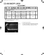
Page 8: ...nnect the DC volt meter between Q1 E and VCC CN1 15pin on X25 and X32 Press the PLAY PAUSE key Confirm that the display is 03 or 05 0 5 0 2V Note Type 4 disc SONY YEDS 18 Test Disc or equivalent LPF Around 47kΩ 390 pF or so 1 With pressing the REPEAT KEY turn the power on to enter the test mode 2 Set the Test disc to Disc NO 1 3 Close the door RF signal in test mode PLAY Perform the tangential and...

Page 9: ...e J 5 e 3 Le 7 H e N 1e g e g e g e g e g e g e 3 L e J 5e N 1 e 7 He 3 LeJ 5 e V KO Y e V4 0Yf J5 7H e e J5e 7He e J5 e 7H e f J5f 7Hf f f W2 6Xf W MI X e 7 HeN 1 e J 5 e 3 Le 7 H e N 1e g e g e g e g e g e g e 3 L e J 5e N 1 e 7 He 3 LeJ 5 e V KO Y e V4 0Yf W2 6Xf W MI X e 7 HeN 1 e J 5 e 3 Le 7 H e N 1e g e g e g e g e g e g e 3 L e J 5e N 1 e 7 He 3 LeJ 5 e V KO Y e V4 0Yf W g W g W g Y g g g ...

Page 10: ...6X hf N hf H e O26X f f 1 f fV R f f V g hg hg 6K he I4 6Kh e I 6Xg fV 1g f V4 g hg hg hg hg hg hg hg hg hg 6Xhf N hf Hhf 3 Le O26X f V KO2 f Ke O2 0M h 3 0M hf V40Mf hf 3 L he N 1 e O26X e O2 e K e O2 0Mh 3 0M he V40M f he 3 Lhe N 1he he he he he he O26X h K O2 h 3 0M H h V40M e he he J 5he 7 Hhe he he eO26Xf KfO2 1f 3 0MhI f V40M 6X f N f H f J 5g 7 Hg J 5 g 6Kf7 H g I 6X J 5h V Yh V he Xh W X g...

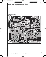
Page 11: ...7 D18 D17 D16 D19 D3 WH6 E10 E11 WH9 WH8 S17 WH7 TEXT CONTROL SYSTEM XS8 SL16 OUTPUT X32 G 8 X32 H 8 OPTICAL OUT POWER X32 3500 10 B 8 X32 D 8 X32 C 8 X32 E 8 X32 F 8 T R G T G R ON STANDBY 7 5V Lch Rch Lch Rch GND 7 5V 5V 5V 5V 5V GND AM25 AM15 AM20 GND 5V 5V AM1 AM5 AM10 AM30 AM35 STB2 5V 5V GND GND 5V 5V 9010 ONLY 7 5V 7010 ONLY 7010 ONLY F 9010 ONLY S GND 7010 ONLY 1 13 168bit C33 W412 W405 C3...

Page 12: ...0 ANALOG SW OP AMP CONVERTER A D RFDC CE 42 TE 41 43 IGEN ADIO AVDD0 AVSS0 46 45 44 47 OVER SAMPLING 69 XRST VDD 14 15 11 12 13 7 8 9 10 5 6 4 2 3 1 ATSK SLT SW MON XLON WFCK SPOB SPOA CLOK SENS SCLK DATA XLAT INTERFACE CPU SQCK SYSM SQSO PWM PROCESSOR SUB CODE SEQUENCER SERVO AUTO 3RD ORDER NOISE SHAPER PWM DIGITAL FILTER LMUT 80 RMUT 79 AVDD2 78 AOUT2 77 AIN2 LOUT2 75 76 AVSS1 AVSS2 73 74 AIN1 7...

Page 13: ...6 25 24 23 22 21 20 19 18 17 16 15 GND GND GND GND GND GND D7 D6 D5 D4 D3 D2 D1 D0 1 2 3 4 5 6 7 8 9 10 11 12 13 14 RWRR RWR RTRN GND GND REM VDD XO XI GND RST WDOUT 17 18 19 20 21 22 23 24 25 26 27 28 29 30 31 32 D3 D4 D5 D6 D7 CSRAM A10 RD A11 A9 A8 A13 WR CS A15 VCC 16 15 14 13 12 11 10 9 8 7 6 5 4 3 2 1 GND D2 D1 D0 A0 A1 A2 A3 A4 A5 A6 A7 A12 A14 A16 NC 86 83 82 81 80 79 78 77 76 85 84 87 88 ...

Page 14: ... 30 TFDR FFDR 32 PWM GENERATOR 35 TEST VSS 34 XTSL 37 TES1 36 VC 38 FE 39 A D OP AMP ANALOG SW CLOCK GENERATOR CORRECTOR DEMODURATOR EFM 16K RAM ERROR 45 RFDC ADIO TE CE 40 SE 41 43 42 44 AVSS3 AVSS0 AVDD0 IGEN ASY0 ASYMMETRY ASY1 BIAS RFAC 46 47 48 49 50 51 52 AVDD3 VSS FILI DIGITAL CLTV FILO DIGITAL PCO 55 53 54 56 57 58 64 66 65 69 68 67 LOGIC XVSS XTA0 TIMING XTA1 EMPH XVDD 61 63 62 BCK D A IN...

Page 15: ...P2 40V B 7 8 5 T E K 4 7 5V 2 F 40V 3 GND 5 C49 3300u10 7 5V R86 15K 40V C52 220u50 R88 100 R87 100 0 01 C51 C50 47u100 270 R84 1W 3300u25 C47 100uH 7 5V 7 5V L4 C48 1000P B 360 R83 B 0 01 C46 0 01 C45 10 9 12 11 14 13 4 3 2 1 W300 K AC 120V E 2 1 3 2 1 C84 3 2 1 47u10 C31 C32 0 01 E3 WIRE CLAMPER DOUT 5V GND Q7 8 IC3 6 19 20 20 R203 C155 0 47 C44 0 01 R209 330 330 R210 R207 330 330 R208 5V 230V B...

Page 16: ... CP1 33 P34 P32 P33 28 29 30 P35 P17 31 32 66 68 67 65 64 100Kx15 NX NX P16 34 35 P15 P14 36 37 38 63 62 61 44 41 P12 P11 39 40 P10 P9 P8 42 43 59 58 57 56 55 P5 P7 P6 45 46 P4 P3 47 48 49 52 54 53 51 50 88 12G 52 P2 P1 9G 50 51 10G 11G 53 54 49 48 85 87 86 13G 14G 55 56 57 15G 16G NP 58 59 90 89 92 91 CP2 100Kx15 F2 F2 61 62 1K 220P R189 1K C124 220P R190 C125 R191 1K C126 220P 74 P26 56 53 P6 51...

Page 17: ...1 S12 JOG CN7 D15 D14 IC14 15 uPD780204 038 Q5 6 2SC3246 J K D13 15 B30 2493 05 D16 19 36 37 B30 2532 05 CD 4900M K 3 3 DPF J9030 T E 3 3 X32 C 8 5 0V 4 9V 5 0V 5 0V 5 0V 2 2V 2 4V 5 0V STANDBY 4 6V 34 1V 34 1V 34 1V 34 1V 34 1V 34 1V 34 1V 34 1V 34 1V 34 1V 34 1V 34 1V 34 1V CAUTION For continued safety replace safety criti cal components only with manufacturer s recommend ed parts refer to parts...

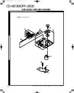
Page 18: ...204 PU 203 632 DM FM 206 208 807 AB 2x25 N39 2025 46 1 2 3 A B Parts with exploded numbers larger than 700 are not supplied CD 4900M DPF J9030 24 EXPLODED VIEW MECHANISM ...

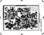
Page 19: ...E RING E RING E RING WASHER WASHER WASHER WASHER 3x27 N83 2004 45 N29 0035 05 N39 2025 46 N30 3003 46 N29 0207 04 N29 0208 04 N29 0209 04 N19 1096 04 N19 0921 04 N19 1171 04 N19 1105 04 N09 5187 08 Cx2 J N N Y Y J N M M M W W V V V V Sx2 Sx2 L L L O Nx6 N Kx2 Nx2 K K Kx2 Q Mx4 Mx2 Nx2 Rx2 Kx3 N Xx2 X X X V V T U W W 64 E Zx4 E E Z Z Z Z CD 4900M DPF J9030 X32 3502 74 A 8 X32 C 8 857B 608 609 601 6...

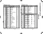
Page 20: ... Q Russia H Korea M Other Areas indicates safety critical components Ref No Add ress New Parts Parts No Description Desti nation Re marks 601 1C A01 3738 08 METALLIC CABINET 602 1C A09 0374 08 BATTERY COVER 602 1C A09 1176 08 BATTERY COVER KEYBOARD 603 2C A21 3811 08 DRESSING PANEL K 603 2C A21 3812 08 DRESSING PANEL TE 604 2C A21 3809 08 DRESSING PANEL K 604 2C A21 3810 08 DRESSING PANEL TE 605 2...

Page 21: ...a I Malaysia Y PX Far East Hawaii T England E Europe G Germany V China Shanghai Y AAFES Europe X Australia Q Russia H Korea M Other Areas indicates safety critical components Ref No Add ress New Parts Parts No Description Desti nation Re marks X1 L78 0299 05 RESONATOR 16 93M X2 L78 0605 05 RESONATOR 8 38MHZ CP1 R90 0875 05 MULTI COMP 100KX15 VR1 R12 3101 05 TRIMMING POT 22K D1 2 HSS104 DIODE D1 2 ...

Page 22: ...V China Shanghai Y AAFES Europe X Australia Q Russia H Korea M Other Areas indicates safety critical components Ref No Add ress New Parts Parts No Description Desti nation Re marks X1 L77 2226 05 CRYSTAL RESONATOR 16 9344MHZ X2 L78 0615 05 RESONATOR 12 5MHZ X3 L78 0674 05 RESONATOR 3 64MHZ X4 5 L78 0284 05 RESONATOR 5MHZ CP1 4 R90 0875 05 MULTI COMP 100KX15 CP5 6 R90 0479 05 MULTI COMP 100KX12 R1 ...

Page 23: ... PX Far East Hawaii T England E Europe G Germany V China Shanghai Y AAFES Europe X Australia Q Russia H Korea M Other Areas indicates safety critical components Ref No Add ress New Parts Parts No Description Desti nation Re marks D1 11 1SS133 DIODE D20 D3SBA20F03 DIODE D20 RBV 402LFA DIODE D21 MTZJ7 5 B ZENER DIODE D21 RD7 5JS B2 ZENER DIODE D22 DLM10C DIODE D23 HSS104A DIODE D23 1SS133 DIODE D24 ...

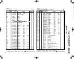
Page 24: ... 479 mm 18 7 8 Weight Net 9 0 kg 19 8 lb Ref No Add ress New Parts Parts No Description Desti nation Re marks 58 2E J21 6571 08 PLATE SLIDER A 60 2E J21 6575 08 PLATE SUPPORT B 62 2D D13 1852 08 GEAR B 63 2D D13 1853 08 GEAR C 64 1E J90 0855 08 GUIDE DISC U 65 2E J19 5894 08 HOLDER DISC U 67 2E G01 4057 08 SPG SLIDER 69 2E G01 4062 08 SPG DAMPER A 70 2E G01 4063 08 SPG DAMPER B 72 2E G01 4065 08 S...

Reviews: