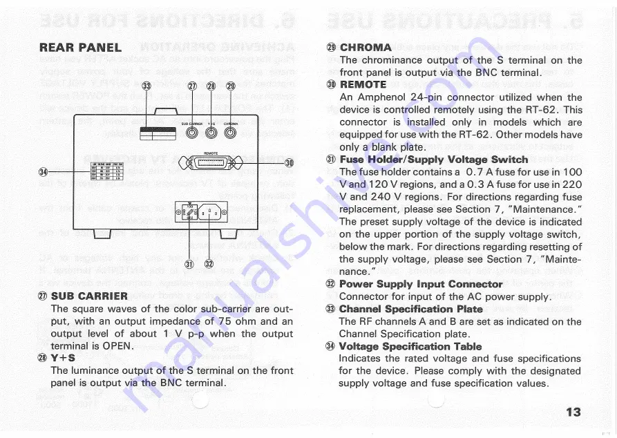
R E A R P A N E L
® S U B CARRIER
The square waves of the color sub-carrier are out-
put, with an output impedance of 76 ohm and an
output level of about 1 V p-p when the output
terminal is OPEN.
® Y + S
The luminance output of the S terminal on the front
panel is output via the BNC terminal.
® CHROMA •
The chrominance output of the S terminal on the
front panel is output via the BNC terminal.
® REMOTE
An Amphenol 24-pin connector utilized when the
device is controlled remotely using the RT-62. This
connector is installed only in models which are
equipped for use with the RT-62. Other models have
only a blank plate.
® Fuse Holder/Supply Voltage Switch
The fuse holder contains a 0.7 A fuse for use in 100
V and 120 V regions, and a 0.3 A fuse for use in 220
V and 240 V regions. For directions regarding fuse
replacement, please see Section 7, "Maintenance."
The preset supply voltage of the device is indicated
• on the upper portion of the supply voltage switch,
below the mark. For directions regarding resetting of
the supply voltage, please see Section 7, "Mainte-
nance/'
® Power Supply Input Connector
• Connector for input of the
AC
power supply.
® Channel
Specification
Plate
The RF channels A and B are set as indicated on the
Channel Specification plate.
® Voltage Specification Table
Indicates the rated voltage and fuse specifications
. for the device. Please comply with the designated
supply voltage and fuse specification values.
13


