38
RIGHT OVEN:
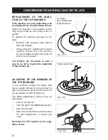
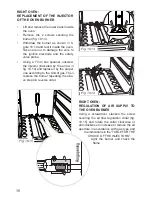
REPLACEMENT OF THE INJECTOR
OF THE OVEN BURNER
Lift and remove the lower panel inside
•
the oven.
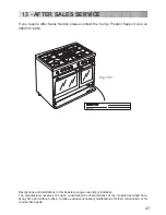
Remove the 2 screws securing the
•
burner (fig. 10.13).
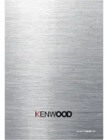
Withdraw the burner as shown in fi
-
•
gure 10.14 and rest it inside the oven.
Take care not to damage the wire to
the ignition electrode and the safety
valve probe.
Using a 7 mm box spanner, unscrew
•
the injector (indicated by the arrow in
fig. 10.14) and replace it by the proper
one according to the kind of gas. Then
replace the burner repeating the abo-
ve steps in reverse order.
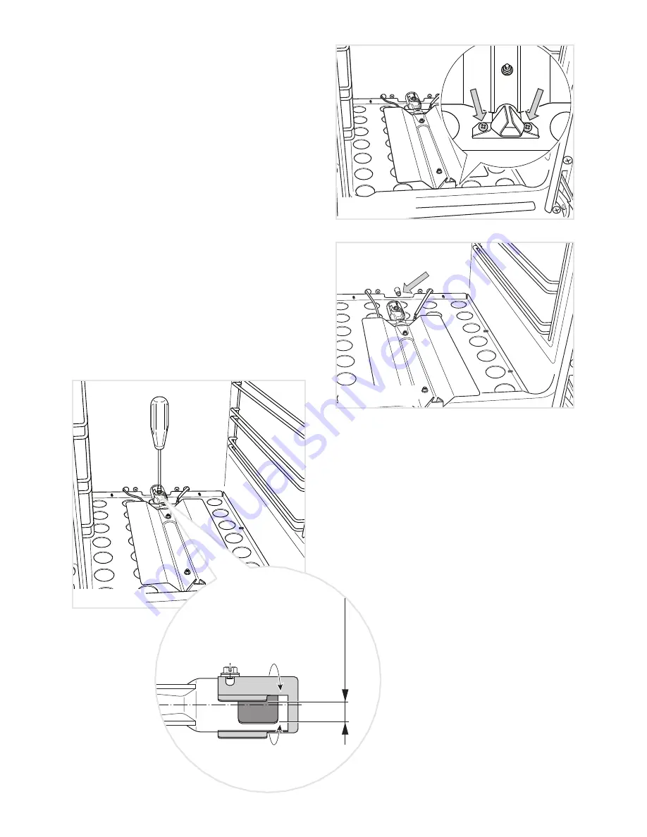
Ring opening
Fig. 10.15
Fig. 10.14
Fig. 10.13
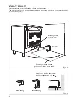
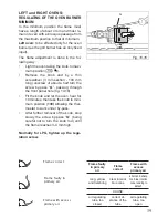
RIGHT OVEN:
REGULATION OF AIR SUPPLY TO
THE OVEN BURNER
Using a screwdriver, slacken the screw
securing the air flow regulation collar (fig.
10.15) and rotate the collar clockwise or
anti-clockwise to increase or reduce the air
aperture in accordance with gas type and
the indications in the “TABLE FOR THE
CHOICE OF THE INJECTORS”.
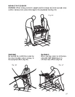
Light the burner and check the
flame.