background image

25

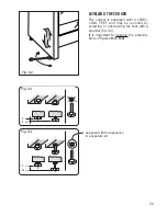
Fig. 8.9

FITTING THE OVEN OUT

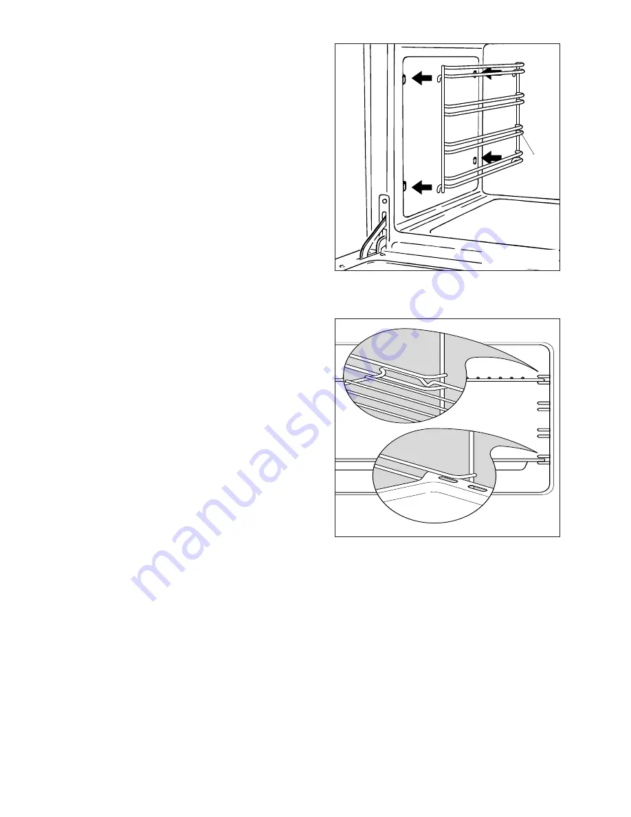
– Hang up the wire racks “G” on the oven

walls (fig. 8.8).

– Slide the required shelf and tray etc. in

using the guides (fig. 8.9).
The rack must be fitted so that the safe-
ty catch, which stops it sliding out, faces
the inside of the oven (fig. 8.9).

– To dismantle, operate in reverse order.   

INSIDE OF OVEN

– The oven should always be cleaned

after use when it has cooled down.

– Remove and refit the side runner

frames as described on the next
chapter.

– The cavity should be cleaned using a

mild detergent solution and warm
water.

– Suitable proprietary chemical cleaners

may be used after first consulting with
the manufacturers recommendations
and testing a small sample of the
oven cavity.

– Abrasive cleaning agents or scouring

pads/cloths should not be used on
the cavity surface.

– Side runner frames, tray and rack can

be removed and washed in the sink. 

NOTE: The manufacturers of this appli-
ance will accept no responsibility for
damage caused by chemical or abrasive
cleaning.

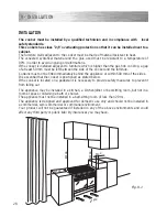
Fig. 8.8

G

Summary of Contents for CK 704

Page 1: ...Instructions for use Installation advice DUAL FUEL DOUBLE OVEN COOKER CK 704 GB ...

Page 2: ...2 ...

Page 3: ...commendations 5 Cooking Hob 6 Control Panel 7 How to use the cooking hob 8 9 How to use fan main oven 10 13 How to use the conventional oven 14 15 Cooking guide 16 How to use and set the electronic programmer 17 20 Cleaning maintenance 21 26 Advice For The Installer 27 Installation 28 32 Gas installation 33 37 Electrical installation 38 39 Guarantee 40 After sales service 41 Read the instructions ...

Page 4: ...e It may be useful in the future either to yourself or to others in the event that doubts should arise relating to its operation This appliance must be used only for its intended purpose that is for the domestic cooking of foodstuffs Any other form of usage is to be considered as inappropriate and therefore dangerous The manufacturer declines all responsibility in the event of damage caused by imp...

Page 5: ...pplied with a protective film on steel and alumini um parts This film must be removed before using the appliance WARNING When correctly installed your product meets all safety requirements laid down for this type of product category However special care should be taken around the rear or the underneath of the appliance as these areas are not designed or intended to be touched and may contain sharp...

Page 6: ...ple ring burner TR 3 50 kW 2 Semi rapid burner SR 1 75 kW 3 Rapid burner R 3 00 kW 4 Auxiliary burner A 1 00 kW 5 Semi rapid burner SR 1 75 kW 6 Auxiliary burner A 1 00 kW 1 COOKING HOB Note The electric ignition is incorporated in the knobs ...

Page 7: ...nic programmer Main oven only 10 Conventional oven temperature knob 11 Conventional oven switch knob Pilot lamps 12 Main oven temperature indicator light 13 Conventional oven temperature indicator light 2 CONTROL PANEL 4 11 10 13 Please note This appliance incorporates a safety cooling fan which you will hear oper ating whenever the oven or grill are in use This fan may continue to run for several...

Page 8: ...diate operating can be achieved by positioning the control knob indicator between the maximum and minimum setting but not between the maximum and off positions LIGHTING THE BURNERS To ignite the burner 1 Lightly press and turn the knob anti clockwise and position the knob sym bol to the indicator printed on the control panel fig 3 2 2 Press the knob to operate the electric ignition or in the case ...

Page 9: ...he control panel near each knob there is a diagram that indicates which burner is controlled by that knob Select the burner that is most suitable for the diameter and capacity of the pan to be used As an indication the burners and the pans must be used in the following way It is important that the base diameter of the pot is at least the same diameter as the burner ring to obtain an efficient heat...

Page 10: ...ctrical resistances OPERATING PRINCIPLES Heating and cooking in the FAN oven are obtained in the following ways a by forced convection A fan sucks in the air contained in the oven muffle which sends it through the circular heating element and then sends it back through the muffle Before the hot air is sucked back again by the fan to repeat the described cycle it envelops the food in the oven provo...

Page 11: ...e switch knob on the desired program and select the required temperature To set the temperature it is necessary to make the chosen number printed on the knob to match with the indicator on the control panel The elements will turn ON or OFF automatically according to the energy need which is determined by the thermostat OVEN LIGHT By turning the knob onto this setting we light the oven cavity The o...

Page 12: ...or cooking with a broiler browning crisping au gratin toasting etc HOT AIR COOKING The circular element and the fan are on The heat is diffused by forced convection and the temperature must be regulated between 50 and 250 C with the thermostat knob It is not necessary to preheat the oven Recommended for For foods that must be well done on the outside and tender or rare on the inside i e lasagna la...

Page 13: ...ether with the food when the oven has reached the desired temperature Check the cooking time and turn off the oven 5 minutes before the theoretical time to recuperate the stored heat SIMULTANEOUS COOKING OF DIFFERENT FOODS The FAN consents a simultaneous het erogeneous cooking of different foods Different foods such as fish cake and meat can be cooked together without mixing the smells and flavour...

Page 14: ... hot Care should be taken to avoid touching heating elements inside the oven OPERATING PRINCIPLES Heating and cooking in the CONVEN TIONAL oven are obtained in the follow ing ways a by normal convection The heat is produced by the upper and lower heating elements b by radiation The heat is radiated by the infra red grill element use with the oven door closed 1 2 5 1 5 0 1 7 5 2 0 0 2 2 5 1 0 0 250...

Page 15: ...re the same cook ing temperature both internally and externally i e roasts spare ribs meringue etc OVEN COOKING Before introducing the food preheat the oven to the desired temperature For a correct preheating operation it is advisable to remove the tray from the oven and introduce it together with the food when the oven has reached the desired temperature Check the cooking time and turn off the ov...

Page 16: ...80 190 4 5 30 40mins ROAST MEATS Beef medium joint 190 5 20 25 mins lb 20mins Lamb 190 5 25 30mins lb 25mins Pork 190 5 30mins lb 30mins Chicken 190 5 20 25mins lb 30mins Turkey 180 4 15 20mins lb 20mins Stews Casseroles 170 3 11 2 2hours Temperature and times given are approximate as they will vary depending on the quality and amount of food being cooked Remember to use ovenproof dishes and to ad...

Page 17: ...lock go to zero and cancels the set programs Description of the buttons Timer Cooking time End of cooking time Manual position and cancellation of the set cooking program Advance the time for of all pro grams Decrease the program time and changing the frequency of the audible signal The electronic programmer performs the following functions 24 hours clock with illuminated dis play Timer up to 23 h...

Page 18: ... the desired time in the panel fig 7 4 Having finished the setting the clock hour will appear on the panel and the symbol will be lit The countdown will start immediately and may be seen at any moment on the panel by simply pressing the button At the end of the time the symbol will be switched off and an intermittent buzzer will go off this can be stopped by pressing any of the buttons SETTING THE...

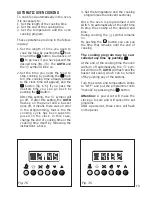
Page 19: ...el Fig 7 6 Fig 7 5 AUTOMATIC OVEN COOKING To cook food automatically in the oven it is necessary to 1 Set the length of the cooking time 2 Set the end of the cooking time 3 Set the temperature and the oven cooking program These operations are done in the follow ing way 1 Set the length of time you need to cook the food by pushing the but ton and the button to advance or to go back if you have pass...

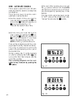
Page 20: ...me you need to cook the food by pushing the but ton and the button to advance or to go backwards Fig 7 7 This sets the desired stop time or 2 Set the time you need the food to stop cooking by pushing the but ton and the button to advance or to go backwards if you have passed the desired time Fig 7 8 AUTO and the symbol will be on Then set the temperature and the cook ing program see the relevant s...

Page 21: ...roducts Dry preferably with a soft cloth Acidic substances like lemon juice tomato sauce vinegar etc can damage the enamel if left in contact for too long REPLACING THE OVEN LIGHT BULB Switch the cooker off at the mains When the oven is cool unscrew and replace the bulb with another one resistant to high temperatures 300 C voltage 230 V 50 Hz 15 W E14 Note Oven bulb replacement is not covered by y...

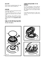
Page 22: ...pective hous ings Note To avoid damage to the electric ignition do not use it when the burn ers are not in place CORRECT REPLACEMENT OF THE BURNERS It is very important to check that the burner flame distributor F and the cap C has been correctly positioned see fig 8 1 failure to do so can cause serious problems Check that the electrode S fig 8 1 is always clean to ensure trouble free sparking GAS...

Page 23: ... ring burner must be correctly positioned see fig 8 2 8 3 the burner rib must be enter in their logement as shown by the arrow Then position the cap A and the ring B fig 8 3 The burners must be correctly positioned so that they cannot rotate fig 8 3 ...

Page 24: ...COMPARTMENT The storage compartment is accessible through the pivoting panel fig 8 7 Fig 8 6 Do not use harsh abrasive clean ers or sharp metal scrapers to clean the oven door glass since they can scratch the surface which may result in shattering of the glass Do not store flammable material in the oven or in the storage com partment ...

Page 25: ...nd refit the side runner frames as described on the next chapter The cavity should be cleaned using a mild detergent solution and warm water Suitable proprietary chemical cleaners may be used after first consulting with the manufacturers recommendations and testing a small sample of the oven cavity Abrasive cleaning agents or scouring pads cloths should not be used on the cavity surface Side runne...

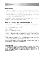
Page 26: ...nges fig 8 10B Hold the door as shown in fig 8 10 Gently close the door and withdraw the lower hinge pins from their location fig 8 10C Withdraw the upper hinge pins from their location fig 8 10D Rest the door on a soft surface To replace the door repeat the above steps in reverse order Fig 8 10D Fig 8 10C Fig 8 10B Fig 8 10A REMOVING THE OVEN DOOR Fig 8 10 ...

Page 27: ...fety standards Failure to observe this rule will invalidate the warranty The electrical mains outlet if located behind the cooker must not be higher than 18 cm above the floor level Some appliances are supplied with a protective film on steel and aluminium parts This film must be removed before using the cooker Advice for the installer ...

Page 28: ...een the side of the cooker and the furniture Curtains must not be fitted immediately behind the appliance or within 500 mm of the sides It is essential that the cooker is positioned as stated below If the cooker is located on a pedestal it is necessary to provide safety measures to prevent it from falling out The appliance may be installed in a kitchen a kitchen diner or bed sitting room but not i...

Page 29: ...lied with the appliance in a separate kit LEVELLING THE COOKER The cooker is equipped with 4 LEVEL LING FEET and may be levelled by screwing or unscrewing the feet with a spanner fig 9 2 It is important to observe the prescrip tions of figures 9 3 9 4 ...

Page 30: ...upright position fig 9 6 WARNING When moving the cooker to its final position DO NOT DRAG fig 9 7 Lift feet clear of floor fig 9 5 MOVING THE COOKER WARNING When raising the cooker to an upright position always ensure that two peo ple carry out this manoeuvre to pre vent damage to the adjustable feet fig 9 5 ...

Page 31: ...u can buy the type of bracket shown here from most plumbing and DIY shops Wall fixing Floor fixing Brackets Existing slot in rear of cooker Dotted line showing the position of cooker when fixed Dimension is in millimetres 3 Outline of cooker backplate at the engagement slot Fig 9 8 ...

Page 32: ...tside air in which case no permanent ventilation is required For rooms with a volume greater than 10 m3 no permanent ventilation is required NB Regardless of room size all rooms containing the appliance must have direct access to the outside air via an openable window or equivalent Where there are other fuel burning appliances in the same room BS 5440 2 2000 should be consulted to determine the co...

Page 33: ...talled Gas Safety Installation Use Regulations Building Regulations British Standards Regulations for Electrical Installation Installation and service of any gas product must be made by a suitably qualified person competent on the type of product being installed or serviced and holding a valid certifi cate of competence for the work being carried out Currently the proof of competence is the Accred...

Page 34: ...as inlet at the rear of the cooker interposing the gasket Check the correct positioning of the connector as shown and always use two suitable spanners Fig 10 1 Connect the gas supply to the right or left gas inlet at the rear of the cooker The pipe is not to cross the cooker Close the unused end inlet pipe with a plug interposing the gasket To avoid damage to the appliance gas rail inlet pipe tigh...

Page 35: ...35 IMPORTANT PRESCRIPTIONS FOR GAS CONNECTION 700 mm Rear wall Suggested area for gas mains connection 200 mm Fig 10 3 1 2 BSP male Left gas inlet pipe Right gas inlet pipe Plug Fig 10 2 ...

Page 36: ...ula tion screw Fig 10 5 Fig 10 4a J J Fig 10 4b INJECTORS REPLACEMENT OF TOP BURNERS If the injectors are not supplied they can be obtained from the Service Centre The diameter is marked on the injector in cents of millimetre Select the injectors to be replaced according to the Table for the choice of the injectors page 37 To replace the injectors Remove the gratings the burner and the covers Usin...

Page 37: ...2 X Semi rapid SR 1 75 0 45 65 97 Z Rapid R 3 00 0 75 85 115 Y Triple ring TR 3 50 1 50 95 135 T Nominal Power kW Reduced Power kW Ø injector 1 100 mm Ø injector 1 100 mm LUBRICATION OF THE GAS TAPS If a tap becomes stiff do not force contact your local Service Agent IMPORTANT All intervention regarding installation maintenance and conversion of the appli ance must be fulfilled with original facto...

Page 38: ...ontacts of 3 mm between the appliance and the mains The power supply cable must not touch the hot parts and must be posi tioned so that it does not exceed 75 C at any point Once the appliance has been installed the switch must always be accessible 11 ELECTRICAL SECTION IMPORTANT The cooker must be installed in accordance with the manufacturer s instructions Incorrect installation for which the man...

Page 39: ... earth wire to the terminal PE as shown in figure 11 1 Take up any slack in the cable and secure with the cable clamp D Replace the cover A N B The earth conductor must be left about 3 cm longer than the others Fig 11 1 D B PE A N L FEEDER CABLE SECTION TYPE HO5RR F 230 V 3 x 2 5 mm2 230 V PE N L1 L2 Fig 11 2 PE Earth N Neutral L Live TECHNICAL DATA 230 V AC 50 Hz Fan Main oven Grill element 2 00 ...

Page 40: ... not misused neglected or damaged it it has not been modified it is not second hand it has not been used commercially you have not fitted a plug incorrectly and you supply your receipt to show when you brought it The appliance has been installed as per the instructions contained within this booklet This guarantee does not affect your statutory rights GUARANTEE ...

Page 41: ...41 Ser Nr If you require After Sales Service contact the MASTERCARE Domestic Appliance Helpline Telephone 08701 565550 AFTER SALES SERVICE ...

Page 42: ...42 ...

Page 43: ...et are given as simply indicative The manufacturer reserves the right considering the characteristics of the models described here at any time and without notice to make eventual necessary modifications for their construction or for commercial needs ...

Page 44: ...code 1103058 ß2 ...

Reviews: