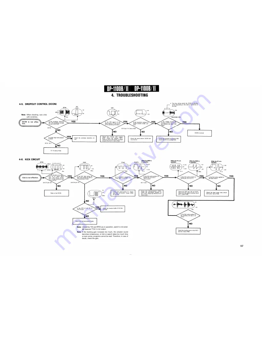
4. TROUBLESHOOTING
-5. DROPOUT CONTROL (DCON)
Note: When checking, use a disc
with scratches.
DCON is not effec
tive.
(IC15 2 3 ),
IC 15 (Servo PCB)
Check the envelope detection cir
cuit.
Check the 114-bit shift register
(IC9). Check the inverter (IC7).
Check to see if the DOCK is o u t p u t
(at pin 3 5 of IC15: Servo PCB).
Check the semi-custom DCON (pin
12 of IC15)
The time during w h i c h the DCON is effective
varies depending on the state of scratches on
the disc.
Check the transistor for control (Q8).
Check the FET for control (Q9).
YES
DCON is normal
6. KICK CIRCUIT
Kick is not effective.
T T A C
While the B W D is
P U P S in operation
While the F F is in
operation
While the B W D is
in operation
While the F F is in
operation
YES
N O
r
Check the semi-custom IC. Check
the TES ( I C 1 3 - 2 / 2 ) . Check RFES
(IC10-2/.2).
Check the inverter buffer IC16 (Ser
vo PCB).
Check the microprocessor m o d e .
Note:
Note:
Unless the TES and RFES are in operation, search is not possi
ble beacuse TTAC is not output.
If the tracking gain increases too m u c h , the actuator sound
becomes conspicuous, or kick or search takes too much time
or even worse, programs cannot be read. Therefore, in case of
doubt, check the gain.
Check the microprocessor m o d e .
Check the associated circuitry of
IC11 ( 2 / 2 ) . Check the PUFB of IC15
(Servo pcb).
Check the KICF (pin 33) of S-IC15.
Check the kick signal inverting circuit
(IC11: Servo PCB).
Check the feed motor a m p circuit
(IC4 ( 2 / 2 ) : Servo PCB)
Check the tracking servo circuit (IC1
and IC2: Servo PCB).
Summary of Contents for DP-1100 B
Page 3: ...D P 1 1 0 0 B II D P 1 1 0 0 B II I BLOCK DIAGRAM ...
Page 32: ...D P 1 1 0 0 B II 1 CIRCUIT DESCRIPTION Disc Scratch Dust RFES D C O N D O C K Fig 1 2A 3 5 ...
Page 112: ...2 IC OPERATION OF EACH CIRCUIT AND D P 1 1 0 0 B II PIN DESCRIPTION Fig 2 4 1 G 1 ...
Page 117: ...DP 1100B II I OPERATION OF MAIN MICROPROCESSOR Fig 3 1D Q data reading flow chart ...


