background image

DPC-781/782/981

3

ADJUSTMENT

1. Test Mode

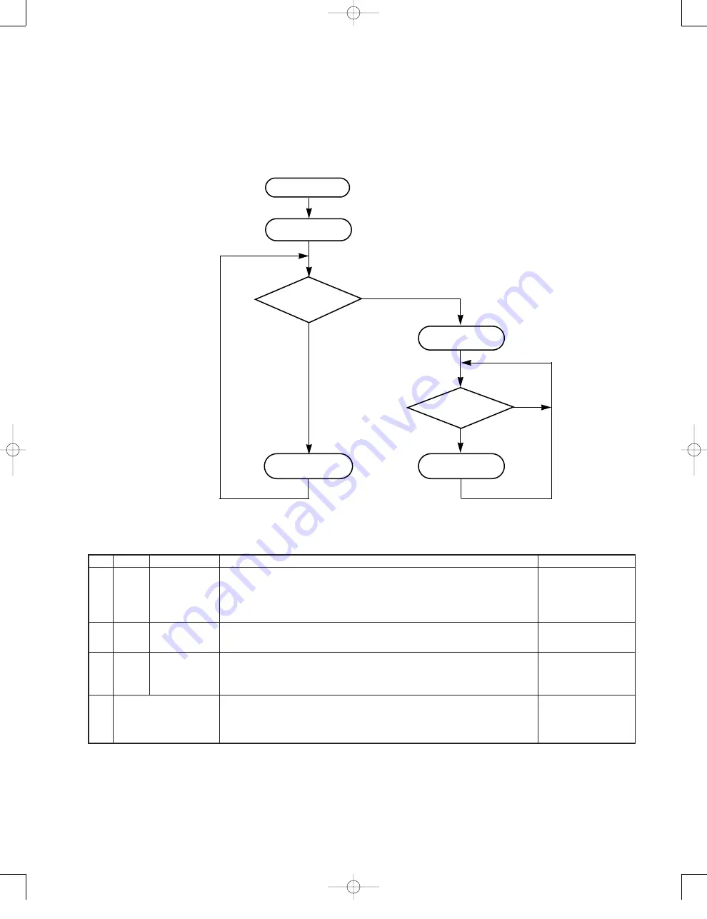
1-1 Setting the test mode

This model can be set to the test mode by shorting
the test-land of the X32 board.

START

Turn on lid

switch

Is test land

shorted?

Test mode pro-

cessing

Is key pushed?

Track No. "01"

is displayed.

TEST MODE

YES

NO

NO

See following table.

Normal operation

No.

Mode

Key Name

Function

TRACK No. display

1

05

PLAY/PAUSE

(

6

)

1. Focus servo.....................................................................................................ON 
2. Tracking servo.................................................................................................ON 
3. Feed servo ......................................................................................................ON
Absolute time at position of limit SW is displayed in time area, then play is started.

05

After 1, 2 and 3 are fin-
ished, track No. played
currently and its play
time are indicated.

2

03

UP

(

¢

)

1. Focus servo.....................................................................................................ON 
2. Tracking servo...............................................................................................OFF 
3. Feed servo ....................................................................................................OFF

03

3

01

STOP

(

7

)

1. Focus servo...................................................................................................OFF 
2. Tracking servo...............................................................................................OFF 
3. Feed servo ....................................................................................................OFF 

✜ 

Test mode can be can celled while pressing the STOP (

7

) Key in 01 mode.

01

4

While pressing the
P. MODE/SEARCH Key, 
turn the AC ON

All LCD is turned ON for 2 seconds. 

ó

All LCD is turned OFF for 2 seconds. 

ó

Returned to normal mode.

1-2 Key and functions avild in test mode

DPC-781/782/981(K) 

1P( 


98.4.24 

23:08 

 y [ W  

6

Summary of Contents for DPC-781

Page 1: ...atteries and rechargeable batteries Approx 27 5 25 hours Dimensions W x H x D 133 6 mm x 26 5 mm x 151 8 mm Weight net 270 g 9 5 oz SPECIFICATIONS 1 KENWOOD follows a policy of continuous advancements in development For this reason specifications may be changed without notice 2 Sufficient performance may not be exhibited at extremely cold locations where water freezes Notes Notes Refer to parts li...

Page 2: ...e DPC 781 M type A70 1190 05 DPC 782 X type AC adaptor 1 W08 0658 05 E type W08 0659 05 T type W08 0660 05 X type W08 0667 05 M type W09 1251 05 K P type Remote controller assy 1 A70 1037 05 DPC 782 DPC 981 K P type Audio cord E30 2782 05 DPC981 T E type Battery 1 DPC 981 Stereo headphone 1 W01 0946 05 DPC 981 M type W01 0947 05 DPC 981 K P type W01 0954 05 DPC 981 T E type SPECIFICATIONS Top cove...

Page 3: ...rvo ON Absolute time at position of limit SW is displayed in time area then play is started 05 After 1 2 and 3 are fin ished track No played currently and its play time are indicated 2 03 UP 1 Focus servo ON 2 Tracking servo OFF 3 Feed servo OFF 03 3 01 STOP 7 1 Focus servo OFF 2 Tracking servo OFF 3 Feed servo OFF Test mode can be can celled while pressing the STOP 7 Key in 01 mode 01 4 While pre...

Page 4: ... land F1 and F2 to which connect an oscilloscope or AC voltmeters Connect a LPF between Check land T1 and T2 to which connect an oscilloscope or AC voltmeters Connect an oscillo scope as follows CH1 RF Check land RF CH2 T1 Check land TE1 PLAYER SETTING Press the PLAY key Confirm that the display is 05 Press the PLAY key Confirm that the display is 05 Press the PLAY key Confirm that the display is ...

Page 5: ...A C E B D 2 1 3 5 7 4 6 PC BOARD Component side view Refer to the schematic diagram for the value of resistors and capacitors 5 DPC 781 782 K pcb98 3 204 10PM y W 1 ...

Page 6: ...6 PC BOARD Foil side view Refer to the schematic diagram for the value of resistors and capacitors 1 J F H G I 2 3 5 7 4 6 DPC 781 782 K pcb98 3 204 13PM y W 2 ...

Page 7: ...P SPDL SPDL SLED SLED SLTSW GND 41 40 40 R17 10K R22 220 C17 100u10 3 VO EXT 4 2 VDD 1 VSS CE 5 SHORT LAND VCC PD1 PD2 VC 6 GND VR PD 4 5 1 PD1 PD2 2 E 3 15 14 FCS FCS 12 11 10 F A L TRK 9 8 7 LD VCC VC A L 100K 82K 200P 390K R117 L11 B B 47u4 C114 R215 470 R213 6 8K 330K R216 MDP 40 VR1 50K C306 1 C307 1 R327 470K R326 470K R316 470K R325 100K R21 47K 3 GND 4 SUB 2 OUT VCC NC 1 5 R342 4 7K R321 4...

Page 8: ... YES R341 R345 C311 4 7K R423 OFF ON 100K R421 4 7u6 3 4 7u6 3 3 3u4 1 C417 4 7 R411 0 15 C411 47u4 R402 C414 0 047 0 047 C415 2 2 R416 R412 4 7 1 R413 0 15 C412 C413 1 40 39 37 38 42 41 43 44 0 047 C416 100 R350 10u10 C310 34 35 36 1 1K R347 1K R414 VSS D0 11 12 39 40 A5 A3 10 9 44 A4 VCC 43 38 A6 A2 15 36 13 14 37 XOE A8 A0 6 35 41 A7 A1 8 7 42 16 5 31 IC7 8 R343 10K R344 R339 47K 22K 0 01 C311 ...

Page 9: ... BLK AB M2x8 AC M1 7x1 8 N09 3425 08 N09 3424 08 N39 1718 46 1 4 2 5 3 808 809 811 810 1 2 3 A B Parts with exploded view numbers larger than 700 are not supplied DPC 781 782 981 EXPLODED VIEW MECHANISM DPC 781 782 981 K 1P 98 4 2423 08 y W 12 ...

Page 10: ...Bx2 Bx2 Cx2 C C C C X32 3480 11 DPC 781 782 981 663 660 620 661 667 662 605 606 624 664 744 769 668 631 643 745 635 642 650 612 651 652 641 640 641 601 611 653 615 746 B P1 603 604 622 621 621 622 655 610 623 654 636x2 770 725 716 GRN GRN RED 730 NB 130 AAA A 2 OPTICAL OUT 1 2 3 C D Parts with exploded view numbers larger than 700 are not supplied DPC 781 782 981 DPC 781 782 981 K 1P 98 4 2423 08 ...

Page 11: ...9M9 D16 19 B30 2473 05 LED T9E9 D16 23 B30 2473 05 LED P2 D16 23 B30 2473 05 LED X2K2M2 ED1 B38 0161 05 LIQUID CRYSTAL C1 C92 0038 05 CHIP ELE 22UF 16WV C2 CK73GB1C104K CHIP C 0 10UF K C3 CK73FF1C105Z CHIP C 1 0UF Z C4 CK73GB1C104K CHIP C 0 10UF K C5 CK73GB1H103K CHIP C 0 010UF K C6 7 CK73GB1C104K CHIP C 0 10UF K C8 9 CK73GB1H103K CHIP C 0 010UF K 601 1D A02 1367 01 PLASTIC CABINET M9T9E9 601 1D A...

Page 12: ... E11 0371 05 MINIATURE PHONE JACK 3P GREEN J3 E11 0278 05 MINIATURE PHONE JACK 3P 2 5 J4 E11 0244 15 MINIATURE PHONE JACK 4P K9P9M9 J4 E11 0244 15 MINIATURE PHONE JACK 4P P2 J4 E11 0244 15 MINIATURE PHONE JACK 4P T9E9P1 J4 E11 0244 15 MINIATURE PHONE JACK 4P X2K2M2 P1 2D E23 1749 04 TERMINAL J19 5856 04 HOLDER L1 L33 0566 05 SMALL FIXED INDUCTOR L2 L33 0563 15 CHOKE COIL L11 L40 1001 39 SMALL FIXE...

Page 13: ... CHIP R 180 J 1 16W T9E9X2 R314 RK73GB1J103J CHIP R 10K J 1 16W R315 316 RK73GB1J474J CHIP R 470K J 1 16W M9T9E9 R315 316 RK73GB1J474J CHIP R 470K J 1 16W P1M1 R316 RK73GB1J474J CHIP R 470K J 1 16W K2M2P2 R316 RK73GB1J474J CHIP R 470K J 1 16W K9P9X2 R317 RK73GB1J122J CHIP R 1 2K J 1 16W R318 RK73GB1J152J CHIP R 1 5K J 1 16W R319 RK73GB1J182J CHIP R 1 8K J 1 16W R320 RK73GB1J242J CHIP R 2 4K J 1 16...

Page 14: ...RANSISTOR R326 327 RK73GB1J474J CHIP R 470K J 1 16W R328 RK73GB1J104J CHIP R 100K J 1 16W R329 RK73GB1J562J CHIP R 5 6K J 1 16W R330 RK73GB1J432J CHIP R 4 3K J 1 16W R331 RK73GB1J822J CHIP R 8 2K J 1 16W R332 334 RK73GB1J181J CHIP R 180 J 1 16W P2 R332 334 RK73GB1J181J CHIP R 180 J 1 16W X2K2M2 R335 336 RK73GB1J100J CHIP R 10 J 1 16W R337 RK73GB1J131J CHIP R 130 J 1 16W R338 RK73GB1J181J CHIP R 18...

Page 15: ... DIGITAL TRANSISTOR Q24 DTA114TUA DIGITAL TRANSISTOR Q31 32 DTC124EUA DIGITAL TRANSISTOR Q33 2SB970 TRANSISTOR Q34 DTC124EUA DIGITAL TRANSISTOR E9P1X2 Q34 DTC124EUA DIGITAL TRANSISTOR K2M2P2 Q34 DTC124EUA DIGITAL TRANSISTOR K9P9T9 Q34 35 DTC124EUA DIGITAL TRANSISTOR M9M1 Q36 DTA114EUA DIGITAL TRANSISTOR M1 Q37 38 2SC4081 R S TRANSISTOR Q39 2SB970 TRANSISTOR M9M1 Q40 DTA124EUA DIGITAL TRANSISTOR Q4...

Page 16: ... KENWOOD IBÉRICA S A Bolivia 239 08020 Barcelona Spain KENWOOD ELECTRONICS AUSTRALIA PTY LTD A C N 001499 074 P O Box 504 8 Figtree Drive Australia Centre Homebush N S W 2140 Australia KENWOOD LEE ELECTRONICS LTD Unit3712 3724 Level37 Tower1 Metroplaza 223HingFongRoad KwaiFongN T HongKong KENWOOD ELECTRONICS GULF FZE P O Box 61318 Jebel Ali Dubai U A E KENWOOD ELECTRONICS SINGAPORE PTE LTD No 1 Ge...

Reviews: