DV-6050
4
DISASSEMBLY FOR REPAIR
x4
5
BOTTOM VIEW
CN1
CN74
CN15
CN53
CN33
CN55
CN2
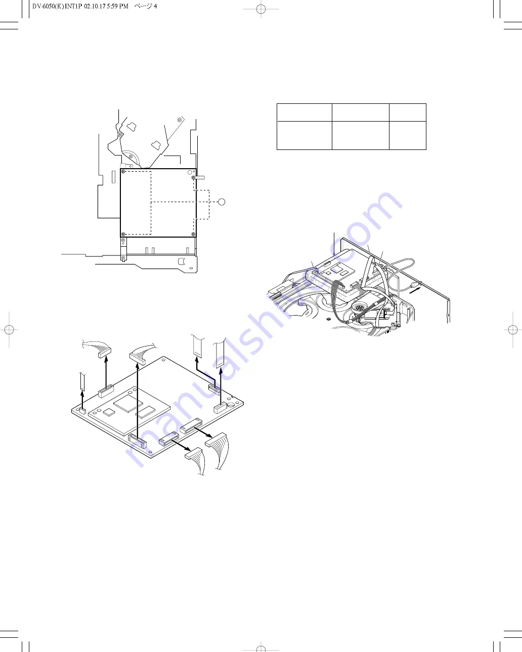
4. Pull out the DVD mechanism horizontally.
5. Up-side-down the DVD mechanism.
6. Remove screws (
5
x4) and DVD B'D.
7. Unplug the connectors ( CN15,CN53,CN55,CN74) and
disconnect 3 flexible cables (CN1,CN2,CN33).
8. For the assembly procedure, follow the item 5 to 3 in
reverse.
9. Set up the DVD B'D on the top as figure 5.
Fig. 3
Fig. 4
10. Connect a jig (E35-2113-05) to CN33 instead of an origi-
nal flexible cable (E35-1990-05).
CN33
Parts No.
Remark
(Flexible cable)
Original
E35-1990-05
22cm
ó
JIG
E35-2113-05
35cm
*
* (This is a jig for video signal adjustment, after adjusted
it put back to an original flexible cable.)
11. Plug in the connectors (CN15,CN53) and connect 2 flexi-
ble cables (CN1,CN2).
* Note : The connectors (CN55, CN74) are for audio sig-
nal line so that no necessary to put it back when
video signal output adjustment.
CN1
CN33
CN53CN15
CN2
GND
Use an Instalting Material
12. Follow the item 2 and 1 in reverse.
13. Gruond DVD B'D and rear panel as figure 5.
14. Follow the video signal output adjustment procedure.
Fig. 5


