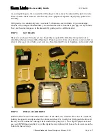
background image

L

R

FRONT SURROUND

CENTER

SUB

WOOFER

MIX LINE

OUTPUT

VIDEO

OUTPUT

COAXIAL

SYSTEM

CONTROL

OPTICAL

7

3

¢

4

¡

1

MIC 2

MIC 1

POWER

-

 ON  

 OFF

ON / STANDBY

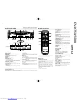
DVD/VCD/CD PLAYER DV-K750

SHUTTLE

0

w

8

/

D.R.I.V.E.

DIGITAL AUDIO

DIGITAL AUDIO

COMPACT

COMPACT

TEXT

TEXT

FL

DISPLAY

CD/VIDEO-CD/DVD PLAYER

DV-K750/S700

SERVICE MANUAL

© 1997-12/B51-5400-00 (K/K) 3207

In compliance with Federal Regulations, following are
reproductions of labels on, or inside the product relating to laser
product safety.

KENWOOD-Crop. certifies this equipment conforms to DHHS
Regulations No. 21 DFR 1040. 10, Chapter 1, Subchapter J.

DANGER : Laser radiation when open and interlock defeated.
AVOID DIRECT EXPOSURE TO BEAM

Panel *
(A60-)

Dressing panel
(A21-3627-12)

Dressing panel *
(A21-)

Dressing panel *
(A21-)

Dressing panel *
(A21-)

Front glass
(B10-2386-12)

Phone jack
(E11-0366-05)

Knob
(K29-6835-12)

Indicator
(B12-0311-04)

Knob
(K27-2449-04)

Knob
(K29-6835-12)

Knob
(K29-6835-12)

Knob
(K29-6945-04)

Phono jack
(E63-0130-08)

Phono jack *
(E63-)

Cylindrical receptacle
(E56-0014-05)

Miniature phone jack
(E11-0188-05)

Oscillating module
(W02-1114-05)

Phono jack
(E63-0068-15)

Phono jack
(E63-0199-05)

Power cord bushing
(J42-0083-05)

AC power cord *
(E30-)

* Refer to parts list on page 36.

Caution : No connection of ground line if disassemble the

unit. Please connect the ground line on rear
panel, PCBs, Chassis and some others.

NOTE : Please replace the mechanism PCB

(W02-2626-05) with new one, if it is
malfunction.

DV-K750/S700(K) 

COVER( 


98.2.2 

16:37 

 y [ W  

2

Summary of Contents for DV-S700

Page 1: ...ation when open and interlock defeated AVOID DIRECT EXPOSURE TO BEAM Panel A60 Dressing panel A21 3627 12 Dressing panel A21 Dressing panel A21 Dressing panel A21 Front glass B10 2386 12 Phone jack E11 0366 05 Knob K29 6835 12 Indicator B12 0311 04 Knob K27 2449 04 Knob K29 6835 12 Knob K29 6835 12 Knob K29 6945 04 Phono jack E63 0130 08 Phono jack E63 Cylindrical receptacle E56 0014 05 Miniature ...

Page 2: ...ds and set the unit to STANDBY mode N O D I S C Beware of condensation When the difference between the internal temperature of the unit and external atmosphere is large dew mist may be produced on the internal parts of the unit In such a case turn the unit ON and leave it for a few hours until the condensation has dried up Be especially careful in the following conditions When the unit is brought ...

Page 3: ...everse 1 SLOW and left right keys Press either key to move the cursor to the left or right or to play a disc at a high speed in the forward or reverse direction During VCD or DVD playback these keys are also used in slow playback Down fi key Press to move the cursor downward 4CD TEXT operation keys TEXT DISPLAY key CD When a CD TEXT disc is used press to switch the character informa tion display A...

Page 4: ...sor This key is also used to start playback of the track chapter or title selected with the numeric keys Fast forward fast reverse 1 SLOW and left right keys Press either key to move the cursor to the left or right or to play a disc at a high speed in the forward or reverse direction During VCD or DVD playback these keys are also used in slow playback Down fi key Press to move the cursor downward ...

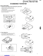
Page 5: ...rew driver into the hole on the bottom chassis 3 Travel the rotary cam to the tray open position 4 Travel the tray to open position by hand 5 Remove the dress panel 2 The Loading Tray 1 Travel the rotary cam to the tray open position 2 Travel the tray to open position by hand 3 Open the hooks of the tray holder and pull out it OPEN CLOSE OPEN TRAY CLOSE TRAY OPEN TRAY PUSH OPEN ...

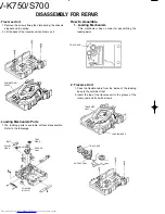
Page 6: ...mble Refer to the followings How to Assemble 1 Loading Mechanism This mechanism has no order for assembling the loading parts 2 Traverse Unit 1 Pass the flexible cable from the inside of the loading base to the outside of that 2 Insert the top of the traverse unit to the groove of the rotary cam and fix it with screws CONNECTING POINT BELT PULLEY GEAR LOADING MOTOR GEAR TRAY GEAR ROTARY CAM TRAY G...

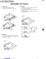
Page 7: ... bottom position counterclockwisely 2 Push the A of the rotary cam to the arrow direction 3 Check the hook to be locked 4 Load the tray to the loading base straightly How to Replace 1 Preparation 1 Short the pickup short lands for protecting the damage of the statics 2 Remove all of the flexible cables on the connection pcb 3 Remove screws to divide the traverse unit TRAY GEAR HooK SHORT ...

Page 8: ... the disc motor unit mount 3 Fix the B screw so that the disc motor unit is at a level with the traverse unit 2 Laser Pickup 1 Remove the screws fixing the pickup 2 Remove the screws fixing the traverse motor 3 Disc Motor 1 Remove the A screw and the B screw in the order Note No need to remove the laser pickup when disc motor replace procedure Pickup TRAVERSE UNIT B SCREW BLK ...

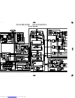
Page 9: ...OR Q 0 5MHz DELAY DEMUX CB CR MATRIX U10 W1 DELAY CB CR Y INT BARS COLOR CR Y CB CLUT SYNC GEN GENERATOR COPY PROTECTION CLOSED CAPTION AND CGMS GENERATORS 10 11 9 13 14 15 12 16 64 59 90 89 83 82 85 86 84 87 AV SYNC SUB PICTURE DECODER DECODER S DRAM VIDEO MIX DECODER 106 159 S DRAM I F 17 22 26 31 39 HOST I F 2 16 18 STREAM SYSTEM 19 17 57 51 32 43 44 45 55 4MB PSRAM SRAM IMB 202 200 CONTROLLER ...

Page 10: ...1 612 FL DISPLAY MUTE3 MUTE4 Q7 9 Q1 4 MUTE1 MUTE1 Q21 24 Y COMP C 75 DRIVER IC303 C 2 2 IC302 75 DRIVER Y 1 2 IC302 75 DRIVER 309 C Q306 6dB FILTER Y 6dB Q301 305 IC301 O S D FILTER SR SL CENTER 5 0 dB SW 2 2 IC17 dB 15 0 IC18 Lch Rch dB 4 5 2 2 1 2 IC8 IC8 IC31 IC20 MIX Lch MIX Rch IC11 IC11 ED1 IC603 VFD C623 POWER BACK UP IC609 CD TEXT CONTROL u COM A601 SENSOR IEC OUT COAX 0 5Vp p 75 Wave len...

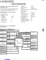
Page 11: ... LETTER BOX q OSD display ON r CENTER CHANNEL ON s SUB WOOFER CHANNEL ON t SURROUND CHANNEL ON non backup Main microprocessor HE643339A48F 1 Block diagram X25 ED1 X25 IC CE DI CL CS SIN SCLK SCLK1 RxD1 IRQ2 SCK0 TxD0 TxD1 RxD0 IRQ1 IRQ0 AN 0 1 AN2 D0 D7 A0 A15 DV S700 DV K750 RD WR 4 ANALOG MUTE SUBW AC 3 KARAOKE DVD LED POWER AS BUSY DATA READ WRITE DATA Address BANK IFL STB IFS IFD CK DATA 3 2 2...

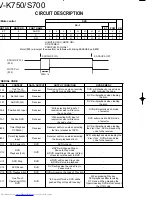
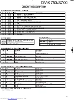
Page 12: ...Mute 1 analog mute 29 AVCC A D standard voltage 30 31 KEY I Key input 1 2 32 33 No use 34 SET I Model selection H DV S700 L DV K750 35 36 SMUTE1 2 I Input port of shuttle switch 1 2 37 SMUTE3 I Output selection of 6 channel H yes L no 38 AVSS GND 39 KARA O KARAOKE output H on L off 40 SUBW O Sub woofer output H on L off 41 AC3 O AC 3 output H on L other 42 IFL2 O Latch signal of serial control to ...

Page 13: ...ODE VIDEO OUT DVD VIDEO OUT VIDEO CD 0 JAPAN 2 NTSC NTSC PAL IMPOSSIBLE TO PLAYBACK NTSC NTSC PAL NTSC 1 NORTH AMERICA 1 NTSC NTSC PAL IMPOSSIBLE TO PLAYBACK NTSC NTSC PAL NTSC 2 EUROPE 2 NTSC CONVERTED PAL PAL PAL NTSC CONVERTED PAL PAL PAL 3 SOUTHEAST ASIA 3 NTSC NTSC PAL PAL NTSC NTSC PAL PAL 4 RUSSIA 5 NTSC CONVERTED PAL PAL PAL NTSC CONVERTED PAL PAL PAL 5 OCEANIA 4 NTSC CONVERTED PAL PAL PAL...

Page 14: ...uras Jamaica Kiribati Marshall Islands Mexico Micronesia Nauru New Zealand Nicaragua Palau Panama Papua New Guinea Paraguay Peru Saint Christopher and Nevis Saint Lucia Saint Vincent and the Grenadines Samoa Solomon Islands Suriname Tonga Trinidad and Tobago Tuvalu Urguay Vanuatu Venezuela Anguilla British Virgin Islands Cayman Islands Christmas Island Cocos Islands Cook Islands Falkland Island Fr...

Page 15: ...t Receiver Receiver will turn on when selecting the timer playback of 6ch DVD will playback when loading the disc If not DVD will send stop code to the receiver 1C11 DVD Power On DVD DVD turns on 1C12 DVD Playback 2ch DVD a DVD will change Stop or Pause to Play mode b DVD code Stop or Pause to Play of receiver will be sent to DVD 1C13 DVD Stop DVD a DVD will receive Stop code b DVD will stop to pl...

Page 16: ...6 TEST MODE 6 1 Key Function 6 2 Display Mode FL display SEL INDICATE 6 3 inspection Mode FL Display SEL INSPECTION SETTING While pressing the 3w 8 STILL PAUSE key push the POWER or MAIN POWER CANCEL Push the STOP 7 key Key Function 4 or Selector Enter 7 Cancel or Back Return No Key Function FL Display 1 3 Enter SEL DOT 2 3 Enter NIAGARA all dots light 3 7 Back SEL DOT 4 4 or Select DOT or SEG SEL...

Page 17: ...on the tray and push the close key 8 MIC2 Jump to track 1 INSPECTION emove the DVD disc on the tray 9 MIC2 Set echo level ECHO MID 0 4 or Select echo level ECHO MID íî HIGHíî LOWíî MID 1 7 Back INSPECTION 2 7 Back SEL INSPECTION 3 7 Cancel NO DISC Inspection Mode FL Display SEL INSPECTION DV K750only HIGH 0dB MID 6dB LOW MIN NATURAL 0cent SHARP 600cent FLAT 600cent HIGH 15 MID 8 LOW 0 NIAGARA Disp...

Page 18: ...nnect the TV monitor and the oscilloscope STILL VR3202 MAIN CBA CYAN 0 7V 0 02Vp p b PAL 1 VIDEO LEVEL Y DISC 100 COLOR BAR Connect the TV monitor and the oscilloscope STILL VR3201 MAIN CBA WHITE 1 00V 0 05Vp p a 2 VIDEO LEVEL C DISC 75 COLOR BAR Connect the TV monitor and the oscilloscope STILL VR3202 MAIN CBA CYAN 0 66V 0 02Vp p b WHITE BURST BURST NTSC PAL 1 00V 0 05Vp p 1 00V 0 05Vp p NTSC PAL...

Page 19: ...V K750 S700 PARTS DESCRIPTION ...

Page 20: ... R166 R162 R158 C131 R168 R48 C108 R126 R122 R118 R125 R121 R117 R63 R59 R55 R64 R60 R56 R33 R29 R25 R34 R30 R26 R171 R177 R254 C28 R20 R16 R18 C138 R179 R12 C20 R6 C18 R8 R94 R92 R182 C246 C136 C186 R103 R102 R175 C133 R173 C135 R172 R174 R262 C103 R115 R114 R113 R265 C123 R151 R145 R147 R255 R256 C73 R88 R87 R86 R85 R260 C94 C90 R106 R108 R259 R107 C97 C96 R76 R75 C65 R71 C63 R69 R95 R97 C59 C61...

Page 21: ...34 33K 5V 5V 12V 12V 12V 12V 12V 12V 12V A YES C C NO A 5V 5V 12V 12V 12V R183 R183 NO NO YES C251 C251 23 2 22 3 21 4 20 5 19 6 18 7 17 8 16 9 15 10 14 11 12 13 VCC2 C004 0 1 C003 0 1 0 1 C002 24 1 8 3 2 9 B4 B1 1 A4 10 A1 5 6 4 7 A3 A2 B2 B3 VCC 16 10 9 8 7 6 5 4 3 2 1 VCC R344 C342 C341 10K 0 01 0 1 R340 C343 10K 0 1 4 3 2 1 TP22 TP17 TP16 TP15 TP14 TP13 TP6 TP11 TP5 TP10 TP4 TP9 TP3 TP8 TP7 23...

Page 22: ...5V 5V R110 100K 100K R111 L R SW 10 S31 S30 S31 S32 SW L H SUBW 12 A B DATA 8200P 10K R146 R147 8 2K R148 8 2K R145 10K 1 FL FR C SR SL 1 3 2 7 4 5 6 R151 20K 8 C123 120P R265 100 R152 20K 100 120P R266 C124 8 VSS 10 9 S30 S31 7 8 6 S31 S30 S32 10 9 11 S20 VSS 0 047 C96 0 01 C91 10u16 C95 51K R107 C97 0 047 R108 390 C98 220u16 0 082 0 47 390 4 3K R106 0 22 C93 C89 0 047 1000P C92 8 1 2 3 7 4 5 6 C...

Page 23: ...04 220u10 100P C233 100P C234 C127 0 01 C128 1000P S31 S32 S31 S30 S41 S42 S41 S40 OUTPUT 10 MIX Rch S41 S42 S41 S40 MIX Lch NORMAL KARAOKE 14 L H KARA 12 S31 S30 S31 S32 MIC2 B GND B MIC1 MICSW 6 1 1 2 3 4 5 6 1 6 3 3K R203 18 SW ML MR 0 01 0 01 22P 22P C181 22P C183 0 01 33 32 31 30 29 28 27 26 25 24 23 100P C225 100P C226 100P 1 2 3 4 5 6 7 8 9 10 11 C174 4 7u35 14 10 OUTPUT 12 KARA Lch Rch KAR...

Page 24: ...AC4V AC26V AC26V AC230V 50Hz AC220V 50Hz AC120V 60Hz T E C K 100 R615 R688 47K AC120V 3 2 AC16V AC16V GND AC16V AC16V AC16V AC16V CONT OUT GND GND D 5V 12V 2200u6 3 C558 C557 2200u16 22uH GND A 5V GND D 3 3V GND 0 082 C512 C560 100u16 3 2 1 GND OUT IN 0 1 130uH C509 2200P 100 R505 3300u35 C554 3300u35 C555 33K R506 CONT 5 1 2 3 4 OUT GND F B IN 12V 12V 12V 12V 12V 12V A 12V A GND A 12V D GND D 5V ...

Page 25: ... 17 16 15 1 WR VCC 2 A12 A14 A13 3 A7 A8 5 A6 A11 6 A4 A5 A9 OE 8 A3 CE1 9 A1 A2 A10 7 4 I O7 A0 I O5 I O6 I O1 I O0 12 11 10 I O4 I O2 I O3 GND 14 13 5V 5V 5V 5V 5V 5V 5V 5V 5V 5V 5V 5V 5V 5V 5V 5V 5V 5V 5V R707 56K R704 56K R705 56K 0 01 C607 1000P C614 R709 56K R710 56K C609 0 01 0 01 C610 R695 47K R694 47K R693 47K R692 47K R676 47K R632 1M 21 C626 0 01 19 18 4 5 6 3 75 R638 2 4 K 11K R651 33K...

Page 26: ...DV K750 S700 33 EXPLODED VIEW MECHANISM 1 1 2 3 A B Parts with exploded view numbers larger than 700 are not supplied ...

Page 27: ...V K750 S700 34 EXPLODED VIEW MECHANISM 2 C D arts with exploded view numbers larger than 700 are not supplied ...

Page 28: ...ø2 6x6 ø3x6 ø3x8 BLK ø3x12 ø3x18 ø3x30 ø4x6 ø3x8 PUSHRIVET N82 2608 46 N89 2606 46 N89 3006 46 N89 3008 45 N09 3450 05 N89 3018 46 N89 3030 46 N89 4006 46 N35 3008 46 N29 0265 15 C AC 110 120V AC 220 240V SYSTEM CONTROL J 3 COAXIAL A 1 OPTICAL J 2 6CH OUTPUT J 4 MIX LINE OUTPUT J 8 VIDEO OUTPUT J 7 S VIDEO X25 H 10 POWER MIC1 MIC2 MIC LEVEL 601 621 657 629 656 635 11P 669 634 30P 650 633 25P 646 6...

Page 29: ...4 MOUNTING HARDWARE 656 1G J42 0083 05 POWER CORD BUSHING 656 1G J61 0101 05 WIRE BAND J19 3327 05 UNIT HOLDER KCTE J61 0307 05 WIRE BAND 658 2E K29 6677 03 KNOB DISPLAY 659 2E K29 6679 03 KNOB OPEN CLOSE 660 2E K29 6835 12 KNOB PLAY STOP 661 2E K29 6945 04 KNOB JOG 662 2E K27 2249 04 KNOB BUTTON 665 1F L07 2467 05 POWER TRANSFORMER K 665 1F L07 2468 05 POWER TRANSFORMER M3 665 1F L07 2468 05 POWE...

Page 30: ...05 CK73FB1H103K CHIP C 0 010UF K CTE C105 CK73FB1H103K CHIP C 0 010UF K M1M2M3 C106 CK73FB1H102K CHIP C 1000PF K CTE C106 CK73FB1H102K CHIP C 1000PF K M1M2M3 C107 108 CC73FSL1H471J CHIP C 470PF J CTE C107 108 CC73FSL1H471J CHIP C 470PF J M1M2M3 C109 CK73FB1H103K CHIP C 0 010UF K C110 CK73FB1H102K CHIP C 1000PF K C111 112 CC73FSL1H121J CHIP C 120PF J D611 B30 2526 05 LED BLUE D612 B30 2513 05 LED R...

Page 31: ...C342 343 CK73FB1E104K CHIP C 0 10UF K C344 CE04KW1C100M ELECTRO 10UF 16WV C345 CK73FB1H103K CHIP C 0 010UF K C346 CK73FB1E104K CHIP C 0 10UF K C350 351 CC73FSL1H470J CHIP C 47PF J C352 354 CC73FSL1H101J CHIP C 100PF J C355 CK73FB1H103K CHIP C 0 010UF K C113 114 CE04KW1C221M ELECTRO 220UF 16WV C121 CK73FB1H103K CHIP C 0 010UF K M1C C122 CK73FB1H102K CHIP C 1000PF K M1C C123 124 CC73FSL1H121J CHIP C...

Page 32: ...X2 L78 0683 05 RESONATOR 12MHZ M1C X601 L78 0678 05 RESONATOR 16MHZ R1 8 RK73FB2A152J CHIP R 1 5K J 1 10W R9 12 RK73FB2A332J CHIP R 3 3K J 1 10W R13 14 RK73FB2A821J CHIP R 820 J 1 10W CTE R13 14 RK73FB2A821J CHIP R 820 J 1 10W M1M2M3 R15 16 RK73FB2A123J CHIP R 12K J 1 10W CTE C356 359 CK73FB1H102K CHIP C 1000PF K C360 361 CC73FCH1H100D CHIP C 10PF D C501 503 C91 1488 05 MF 6800PF 250VAC C504 CK73F...

Page 33: ...K73FB2A302J CHIP R 3 0K J 1 10W CTE R172 RK73FB2A302J CHIP R 3 0K J 1 10W M1M2M3 R173 RK73FB2A222J CHIP R 2 2K J 1 10W CTE R173 RK73FB2A222J CHIP R 2 2K J 1 10W M1M2M3 R174 RK73FB2A302J CHIP R 3 0K J 1 10W CTE R174 RK73FB2A302J CHIP R 3 0K J 1 10W M1M2M3 R175 176 RK73FB2A222J CHIP R 2 2K J 1 10W CTE R175 176 RK73FB2A222J CHIP R 2 2K J 1 10W M1M2M3 R15 16 RK73FB2A123J CHIP R 12K J 1 10W M1M2M3 R17 ...

Page 34: ...0W R501 502 RK73FB2A391J CHIP R 390 J 1 10W R503 RK73FB2A472J CHIP R 4 7K J 1 10W R504 RK73FB2A132J CHIP R 1 3K J 1 10W R505 RK73FB2A101J CHIP R 100 J 1 10W R506 RK73FB2A333J CHIP R 33K J 1 10W R507 RK73FB2A102J CHIP R 1 0K J 1 10W R508 RK73FB2A162J CHIP R 1 6K J 1 10W R177 RK73FB2A302J CHIP R 3 0K J 1 10W CTE R177 RK73FB2A302J CHIP R 3 0K J 1 10W M1M2M3 R178 RK73FB2AR47J CHIP R 0 47 J 1 10W CTE R...

Page 35: ...DE D512 513 UDZ2 7B ZENER DIODE D515 516 S5688B TPB5 DIODE D517 UDZ6 8B ZENER DIODE R509 RK73FB2A112J CHIP R 1 1K J 1 10W R510 RK73FB2A222J CHIP R 2 2K J 1 10W R511 512 RK73FB2A153J CHIP R 15K J 1 10W R513 514 RK73FB2A102J CHIP R 1 0K J 1 10W R515 516 RS14KB3A1R0J FL PROOF RS 1 J 1W R517 RK73FB2A223J CHIP R 22K J 1 10W R518 RK73FB2A163J CHIP R 16K J 1 10W R519 520 RK73FB2A223J CHIP R 22K J 1 10W R...

Page 36: ...OR Q313 314 2SA1576A R S TRANSISTOR Q501 DTC124EUA DIGITAL TRANSISTOR Q502 2SD2061 TRANSISTOR Q503 2SB1370 TRANSISTOR Q504 DTC124EUA DIGITAL TRANSISTOR Q505 506 2SC2003 L K TRANSISTOR Q507 2SB1548 TRANSISTOR Q601 604 2SC4081 R S TRANSISTOR A1 W02 1114 05 OSCILLATING MODULE A601 W02 2571 05 OPTIC RECEIVING MODULE 41 1A J99 0806 08 TRAY 42 1B J19 5924 08 CLAMPER HOLDER 43 1B A11 1142 08 CLAMPER PLAT...

Page 37: ... MOTOR UNIT 80 3C J26 0082 08 CHIP SWITCH UNIT 81 2D J21 6619 08 SUB SHAFT HOLDER 82 2D 3D D10 3807 08 GUIDE SHAFT 83 2D J21 6620 08 NUT STOPPER 84 2D G02 1657 08 NUT STOP SPRING 85 2D D13 1879 08 SCREW NUT 86 2D G02 1658 08 PICKUP STOP SPRING 87 3D T25 0077 08 PICKUP 89 3D A11 1143 08 H CHASSIS B41 1B N80 2608 46 SCREW B42 1B N09 3455 08 SCREW B43 3A N09 3456 08 SCREW B44 3B N80 2608 46 SCREW B45...

Page 38: ... impedance COAXIAL 0 5 Vp p 75 Ω OPTICAL 21 dBm 15 dBm Wave Length 660 nm Input sensitivity impedance DV K750 only 12 5 mV 24 kΩ MIC 1 2 Video Section Video output format For Region 3 6 NTSC PAL For Region 4 5 PAL Video compression VCD MPEG 1 DVD MPEG 2 Horizontal resolution More than 500 lines Video signal to noise ratio More than 60 dB Composite video output level 1 Vp p 75 Ω load sync negative ...

Page 39: ...nd V K750 S700 SPECIFICATIONS Type System DVD video player system Signal read system Semiconductor laser D A Conversion Section D A conversion 24 Bit Oversampling 8 fs Sampling frequency 44 1 48 kHz 4 fs Sampling frequency 96 kHz Audio section Frequency response Sampling frequency 44 1 kHz 4 kHz 20 kHz Sampling frequency 48 kHz 4 kHz 22 kHz Sampling frequency 96 kHz 4 kHz 44 kHz Signal to noise ra...

Reviews: