DV-K750/S700
13
CIRCUIT DESCRIPTION
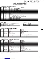
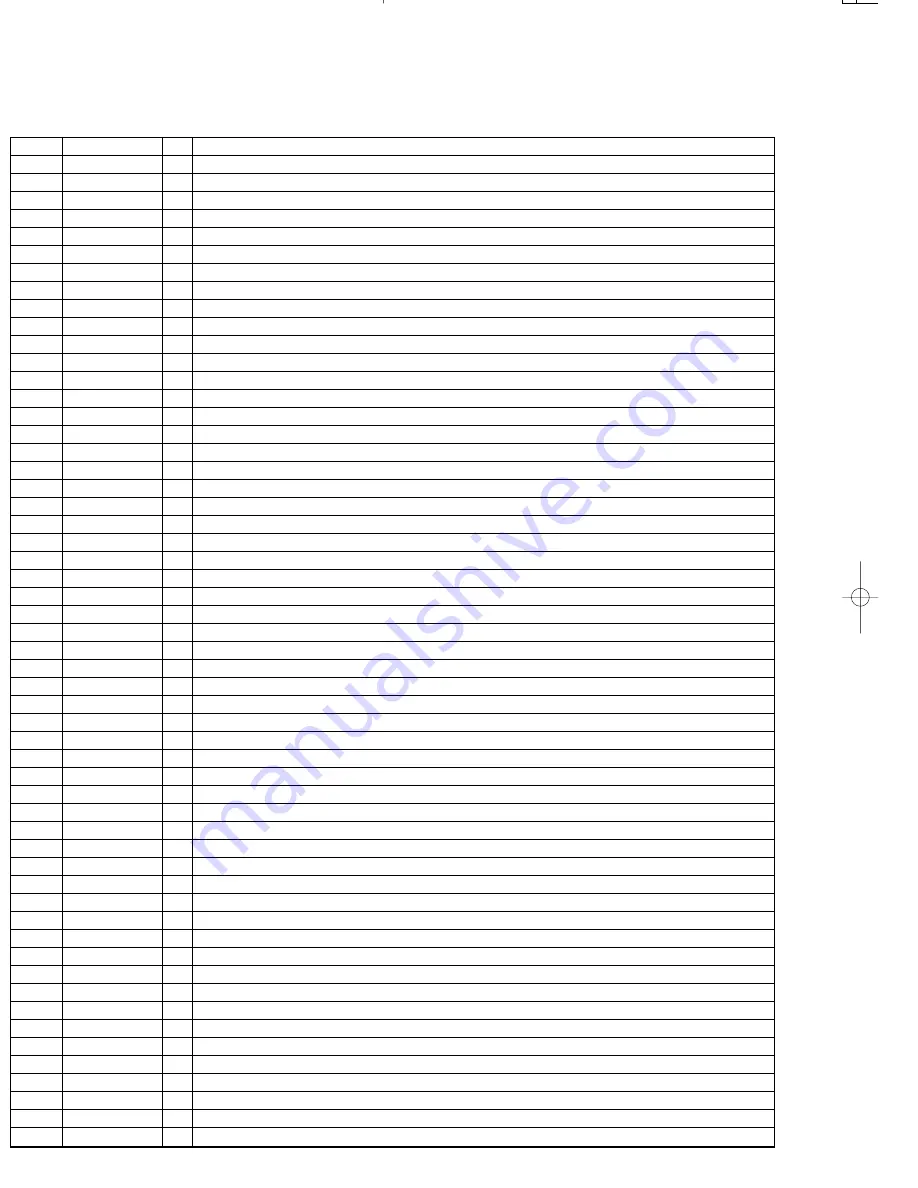
No
Pin Name
I/O
Description
1
/RESET
I
Input port of microprocessor reset
2,3
X/ETAL
I / O Port of ceramic oscillator
4,5
MD0 / 1
I
Operation mode 0 and 1
6
/NMI
–
No use
7
/STBY
–
No use
8
VCC
–
Power supply (+5V)
9
M-SCLK
O
Output port of clock signal to the main processor (DSPSCLK)
10
M-STAT
O
Input port to the main microprocessor (SRDT)
11
M-CMD
O
Output port to the main processor (DQSY)
12
VSS
–
GND
13
POW.LED
O
Standby LED (H : standby)
14
–
–
No use
15
/RAM-CS
O
Access mode of extra-address ( / CS)
16
/RAM-WR
O
Read mode of extra-address ( / WE)
17
/RAM-RD
O
Write mode of extra-address ( / OE)
18
/REMOTE
I
Input port of remote signal
19
/M-READY
I
Ready/resend signal to the main microprocessor
20
/T-DQSY
I
Input port of read signal from CD-TEXT IC (DQSY)
21
SBUSY
I/O Synchro busy signal (BUSY)
22
SDATA
I/O Synchro data signal (DATA)
23
DVD LED
O
DVD LED (H : light, L : dis-light)
24
POWER
O
Power LED (H : ON, L : OFF)
25
MUTE 4
O
Mute 4, analog mute (SW)
26
MUTE 3
O
Mute 3, analog mute (C)
27
MUTE 2
O
Mute 2, analog mute (SL / SR)
28
MUTE 1
O
Mute 1, analog mute
29
AVCC
–
A/D standard voltage
30,31
KEY
I
Key input 1, 2
32,33
–
–
No use
34
SET
I
Model selection (H : DV-S700, L : DV-K750)
35, 36
SMUTE1, 2
I
Input port of shuttle switch 1, 2
37
SMUTE3
I
Output selection of 6 channel (H : yes, L : no)
38
AVSS
–
GND
39
KARA
O
KARAOKE output (H : on, L : off)
40
SUBW
O
Sub woofer output (H : on, L : off)
41
AC3
O
AC-3 output (H : on, L : other)
42
IFL2
O
Latch signal of serial control to electronics volume IC (TC9210P) (STB)
43
IFL1
O
Latch signal of serial control to KARAOKE IC (TC9409BF) (IFL)
44
IFD
O
Serial data output to electronics volume IC and KARAOKE IC (DATA, IFD)
45
IFS
O
Serial clock output to electronics volume IC and KARAOKE IC (CK, IFS)
46
BANKA
O
S-RAM bank selection A
47
VCC
–
Power supply (+5V)
48
CE
I
Chip enable port
49-52
A14-11
I
No use
53-55
A10-8
O
S-RAM access bus address
56
VSS
–
GND
57-64
A7-0
O
S-RAM access bus address
65-72
D0-7
I/O S-RAM access bus data
73
VSS
–
–
74,75
BANK B,C
O
S-RAM bank select b, c
76
VFD-CE
O
VFD display IC serial control latch (CE)
77
OSD-CS
O
OSD display IC serial control latch (STB)
78
OSD/VFD-SD
O
OSD display IC/VFD display ic serial data output (SIN / DI)
79
T-SRDT
I
CD-TEXT IC data input (SRDT)
80
VFD-CL
O
CD-TEXT/OSD/VFD IC serial clock (SCLK / SCLK / CL)
4-2 Pin description.
DV-K750/S700(K)
ADJ/CIR
98.2.2
17:05
y [ W
6
Summary of Contents for DV-S700
Page 19: ...V K750 S700 PARTS DESCRIPTION ...


