DV-K750/S700
CIRCUIT DESCRIPTION
17
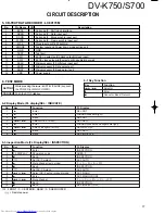
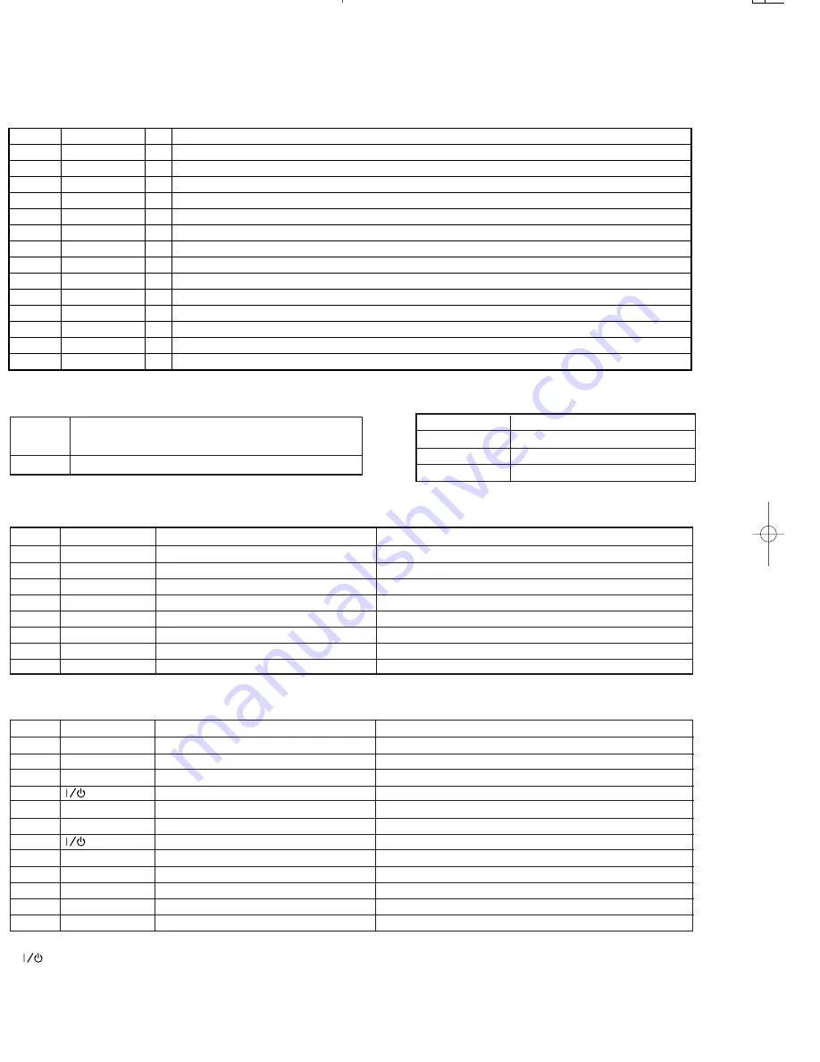
No.
Pin Name
I/O
Description
1
EXCK
I
Sub code IF. Shift clock interface
2
SBSO
I
Sub code IF. Data input port
3
SCOR
I
Sub code IF. Block synchro input port.
4
WFCK
I
Sub code IF. Frame synchro input port.
5
MCK
I
Clock input port(16.9344MHz)
6
XMODE
I
System reset and Power down mode setting port
7
GND
–
GND
8
TEST
I
Test port
9
SW1
I
EXCK I/o select port(L:clock output/H:clock input)
10
SW2
I
EXCK clock pulse width select port(L:double/H:normal)
11
SCLK
I
Microprocessor IF.Shift clock input port
12
SRDT
O
Microprocessor IF.Data output port
13
DQSY
O
Microprocessor IF.Read permit port
14
VDD
–
Power supply
5. CD-TEXT DATA DECODER : LC89170M
✽
F : FRONT / C : CENTER/R : REAR / S : SUB WOOFER
= Remote power
6. TEST MODE
6-1 Key Function
6-2 Display Mode (FL display/SEL : INDICATE)
6-3 inspection Mode (FL Display/SEL : INSPECTION)
SETTING
While pressing the
3w
/
8
(STILL/PAUSE)key,push
the POWER (or MAIN POWER).
CANCEL Push the STOP (
7
) key
Key
Function
4
or
¢
Selector
‰
Enter
7
Cancel or Back (Return)
No.
Key
Function
FL Display
1
3
Enter
SEL:DOT
2
3
Enter
NIAGARA(all dots light)
3
7
Back
SEL:DOT
4
4
or
¢
Select(DOT or SEG)
SEL:SEG
5
3
Enter
NIAGARA(all dots and segments light)
6
4
or
¢
Select( all light or all off)
SEG ALL OFF
7
7
Back
SEL:SEG
8
7
Back
SEL:INDICATE
No.
Key
Function
FL Display
1
3
Enter
INSPECTION
2
FL DISPLAY
Show area code
AREA 0
3
7
Back
INSPECTION
4
Set AC-3 mute on
AC3 AUTO
5
3
Mute channel (auto mode)
F
î
C
î
R
î
S
î
F
✽
6
7
Back
INSPECTION
7
Set AC-3 mute on
AC3 AUTO
8
4
or
¢
Select AC-3 auto or manual mode
AC3 MANU
9
3
Enter
AC3 MANU FRONT
10
4
or
¢
Mute channel
F
íî
C
íî
R
íî
S
íî
F
✽
11
7
Back
INSPECTION
12
7
Back
SEL:INSPECTION
DV-K750/S700(K)
ADJ/CIR
98.2.2
17:06
y [ W
12
Summary of Contents for DV-S700
Page 19: ...V K750 S700 PARTS DESCRIPTION ...


