background image

PHONES

A    SPEAKER     B

BASS

TREBLE

BALANCE

INPUT SELECTOR

MUTING

LOUDNESS

ON

OFF

POWER

ON/STANDBY

MIN

MAX

VOLUME CONTROL

MD

TAPE

TUNER

PHONO

CD

SOURCE DIRECT

thermally reactive advanced instantaneous transistor

T R A I T

L

R

ƒ

SL 16 XS-8

+

+

PHONO

CD

TUNER

TAPE

SYSTEM CONTROL

SPEAKERS

AC OUTLETS

UNSWITCHED

100W MAX.

SWITCHED TOTAL

200W MAX.

AC 100V 50/60Hz

A or B : 4–16

, A and B : 8–16

REC

PLAY

REC

PLAY

MD

SIGNAL GND

L

R

L

R

L

R

B

A

AC 220

AC 230—

240V

AC 110—

120V

STEREO INTEGRATED  AMPLIFIER

KAF-1010/3010R

SERVICE MANUAL

© 1998-3/B51-5415-00 (K/K) 1948

Power lens
(B19-1596-08)

Badge
(B43-0302-04)

Power knob*
(K29-)

Speaker knob
(K29-7376-08)

Control knob
(K29-7383-08)

Selector knob
(K29-7379-08)

Push SW
(S68-0105-08)

Phone jack (D6.5)
(E11-0263-08)

Phono jack (2P)
(E11-0188-05)

Slide switch*
(S62-)

Matellic cabinet
(A01-3630-08)

AC power cord bushing
(J42-0200-08)

AC power cord*
(E30-)

Screw terminal board
(E70-0104-08)

AC outlet*
(E03-)

Slide switch
(S62-0069-08)

System jack (D3.5)
(E11-0333-08)

Phono jack (4P)x3
(E63-0186-08)

Front panel
(A60-1492-08)

Function lens
(B19-1592-08)

Volume knob
(K29-7381-08)

Direct lens
(B19-1593-08)

Front frame*
(A22-)

Illustration is KAF-3010R.

* Refer to parts list on page 18.

Loudness lens
(B19-1594-08)

Caution : No connection of ground line if disassemble the unit.

Please connect the ground line on rear panel, PCBs, Chassis and some others.

Remocon window
(B11-0371-08)

KAF-1010(K) 

1P 


98.4.25 

3:57 

PM 

 y [ W  

2

Summary of Contents for KAF-1010

Page 1: ...ge B43 0302 04 Power knob K29 Speaker knob K29 7376 08 Control knob K29 7383 08 Selector knob K29 7379 08 Push SW S68 0105 08 Phone jack D6 5 E11 0263 08 Phono jack 2P E11 0188 05 Slide switch S62 Matellic cabinet A01 3630 08 AC power cord bushing J42 0200 08 AC power cord E30 Screw terminal board E70 0104 08 AC outlet E03 Slide switch S62 0069 08 System jack D3 5 E11 0333 08 Phono jack 4P x3 E63 ...

Page 2: ... wall outlet Accessory only for regions where use is necessary Operation to reset The microcomputer may fall into malfunction impossibility to operate erroneous display etc when the power cord is un plugged while power is ON or due to an external factor In this case execute the following procedure to reset the microcom puter and return it to normal condition Set the POWER to OFF then while holding...

Page 3: ... 6 TREBLE knob To adjust high frequencies 7 INPUT indicator An indicator lights for the source selected with the INPUT SELECTOR knob 8 VOLUME CONTROL knob Adjust the volume 9 SOURCE DIRECT indicator Usually leave this switch to the on standby position 0 SOURCE DIRECT key To listen to a source with high quality sound PHONES jack Used for headphone listening SPEAKERS A B switches Press to select the...

Page 4: ... ray system Remote control unit KAF 3010R only DISC SKIP key Only used for the Autochanger CD player INPUT SELECTOR keys AUX key does not function with this unit POWER key Use to switch the power ON STANDBY when the POWER switch is turned ON TUNER operation keys MUTING key Mute the sound temporarily VOLUME UP DOWN fi keys Adjust the volume SOURCE DIRECT key To listen to a source with high quality ...

Page 5: ...dness led control signal output 16 MUTE O Mute led control signal output 17 GND Gnd 18 RESET I Reset signal input 19 20 XIN OUT I O Crystal connecting port for clock generation 21 VSS Gnd 22 VAREF Analog reference voltage input 23 KEY I A D key input 24 POW RE O Power relay control signal output 25 VOL UP O Motor volume control 26 VOL DOWN O Motor volume control 27 MUTE O Selector mute control 28 ...

Page 6: ...ENT POINTS ALIGN FOR FIG Unless otherwise specified the individual switches should be set as following POWER ON SPEAKER B SELECTOR PHONO 1 IDLE CURRENT Connect a DC voltmeter as figure W201 Lch W202 Rch MAIN PCB VR101 Lch VR102 Rch MAIN PCB 10mV a VOLUME 0 Dc voltmeter 10mV W201 Lch W202 Rch a ...

Page 7: ...A B D F H J C E G I Refer to the schematic diagram for the value of resistors and capacitors C BOARD Component side view 8 2P 98 4 254 03PM y W 5 ...

Page 8: ...K M O Q S L N P R T 2 1 3 5 7 4 6 Refer to the schematic diagram for the value of resistors and capacitors PC BOARD Component side view 9 10 2P 98 4 254 02PM y W 4 ...

Page 9: ...27K C161 1u100 C233 0 01 C226 0 01 C231 0 01 C225 0 01 C204 R240 47K R185 39 R245 4 7K R255 4 7K 39 R186 27P 100K R184 C274 R236 R235 10K R183 10K R227 10 1W R231 33K R233 22 2uH L101 C230 47u63 R221 1K 2 1 R229 15K C185 R219 3 3K C189 0 1 C187 0 1 10 1W R228 0 1 C188 0 1 C186 2 1 2200P R220 3 3K 2uH L102 R234 22 R222 1K 2200P C184 R232 33K R263 2 2 C197 470u50 1 4W R251 47 1 4W 47 R252 47u25 5 1K...

Page 10: ...127 128 TRAITR2N Q125 126 TRAITR4N Q125 126 4700u50 C203 204 6800u63 C203 204 C604 0 01 C602 0 01 C603 0 01 WH YL GRAY BR RD C591 0 0047 50 60Hz AC230V 50Hz AC IN AC110 120V T200mA F503 F501 F503 T200mA F502 T1 6A L 250V F501 T1 6A L 250V 110 120V 220 240V 0V 110V 0V 110V TF 150 C TF 150 C 220P C177 ON J560 J556 POWER RY GND B C551 470u25 100K R558 F504 C551 OFF 1W ON OFF R401 560 1W C401 1000P C4...

Page 11: ...K 10K 29 25 26 28 27 24 R538 R521 R520 C505 0 01 C504 0 01 R529 100 R530 100 R539 330 R523 330 R531 330 R532 330 R533 100K R534 100K R524 330 330 R540 100 R522 100 100 100 R515 100 R516 100 R541 100K R544 470 R543 470 330 R509 330 R508 330 R507 330 R510 330 R511 330 R542 470 POW RE VOL UP VOL DOWN 24 23 25 26 22 KEY 18 19 20 17 21 X OUT VSS X IN RESET 42 41 40 38 37 35 34 36 39 32 33 31 30 28 29 2...

Page 12: ...01 T502 AC OUTLET SL16 XS8 SW550 N89 3008 45 N89 3008 46 N29 0035 05 N09 3159 08 N09 3095 08 N09 3160 08 N84 3008 46 A B C D E F G Fx4 Dx2 E E SW502 SW401 SW530 VR250 J105 607 620 743 781 783 782 703 601 646 785 784 745 742 704 627 626 613 611 614 602 616 610 615 612 650x2 627 605 642 621 647 640x2 635x2 Bx2 641x2 635x2 626 J101 SD VOLUME POWER POWER PHONES REMOCON LOUD MUTE BASS TREBLE BALANCE IN...

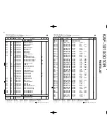
Page 13: ...0UF 50WV C199 CK45FB1H103K CERAMIC 0 010UF K C201 CE04KW1H470M ELECTRO 47UF 50WV C202 CE04KW1H100M ELECTRO 10UF 50WV C203 204 CE04KW1H472M ELECTRO 4700UF 50WV 1 C203 204 CE04KW1J682M ELECTRO 6800UF 63WV 3 C206 CK45FE2H103P CERAMIC 0 010UF P C207 CK45FB1H472K CERAMIC 4700PF K C209 CQ92FM1H473J MYLAR 0 047UF J 601 1A A01 3630 08 CABINET TOP 602 2A A60 1491 08 PANEL AFTER FRONT 1 602 2A A60 1492 08 P...

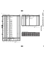
Page 14: ...RAMIC 4700PF K C215 216 CK45FE2H103P CERAMIC 0 010UF P C218 219 CC45FSL1H681J CERAMIC 680PF J 3 C220 CK45FE2H103P CERAMIC 0 010UF P C221 222 CC45FCH1H270J CERAMIC 27PF J C223 CC45FCH1H220J CERAMIC 22PF J C225 226 CK45FE2H103P CERAMIC 0 010UF P C227 228 CC45FSL1H331J CERAMIC 330PF J C229 230 CE04KW1J470M ELECTRO 47UF 63WV C231 CK45FE2H103P CERAMIC 0 010UF P C233 CK45FE2H103P CERAMIC 0 010UF P C251 ...

Page 15: ...TB1366Y TRANSISTOR Q151 KSA992F X TRANSISTOR Q152 154 2SC1740SR TRANSISTOR Q155 2SA933S TRANSISTOR Q156 2SC1740SR TRANSISTOR Q157 158 2SK246GR FET Q201 DTC124ES TRANSISTOR Q202 2SA933S TRANSISTOR Q273 274 KTC2878 TRANSISTOR Q501 DTC144ES TRANSISTOR Q502 503 DTC114TS TRANSISTOR Q504 DTC144ES TRANSISTOR Q550 2SC1740SR TRANSISTOR 3 Q551 2SC1740SR TRANSISTOR M 3 Q552 KSC1845F TRANSISTOR M 3 Q553 KSA91...

Page 16: ...0 Hz Total harmonic distortion 0 06 20 20 000 Hz 35 W 8 Ω 0 01 1 kHz 70 W 8 Ω Frequency responce IHF 78 CD TUNER TAPE MD 5 Hz 100 kHz 0 dB 3 dB PHONO RIAA responce 20 Hz 20 kHz 1 0 dB 1 0 dB Maximum input level PHONO MM 120 mV 0 5 T H D at 1 kHz Signal to noise ratio PHONO MM 77 dB IHF 66 CD TUNER TAPE MD 105 dB IHF 66 PHONO MM 59 dB DIN 50 mW output CD TUNER TAPE MD 61 dB DIN 50 mW output Input s...

Page 17: ... ltaly KENWOOD IBÉRICA S A Bolivia 239 08020 Barcelona Spain KENWOOD ELECTRONICS AUSTRALIA PTY LTD A C N 001499 074 P O Box 504 8 Figtree Drive Australia Centre Homebush N S W 2140 Australia KENWOOD LEE ELECTRONICS LTD Unit3712 3724 Level37 Tower1 Metroplaza 223HingFongRoad KwaiFongN T HongKong KENWOOD ELECTRONICS GULF FZE P O Box 61318 Jebel Ali Dubai U A E KENWOOD ELECTRONICS SINGAPORE PTE LTD N...

Reviews: