KCH-14/15
2
DISASSEMBLY FOR REPAIR
Disassembly Procedure
■
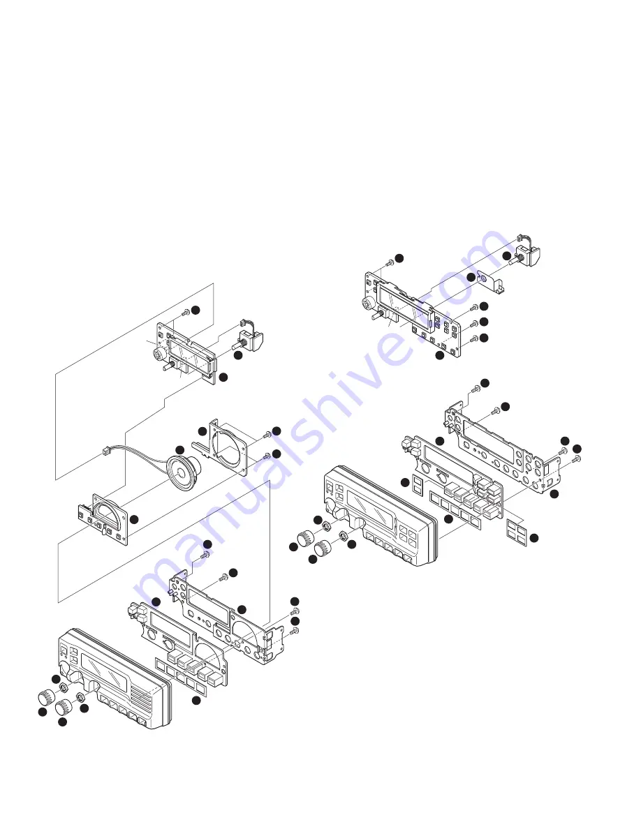
Disassembly of the Display unit (X54-349) : KCH-14
1. Remove the volume knob
z
and selector knob
x
.
2. Remove the 2 hexagon nuts
c
.
3. Remove the cable from the display unit (X54-349 A/3)
connector (CN4), and remove the channel encoder
v
.
4. Remove the 4 screws
b
holding the speaker.
5. Remove the cable from the display unit (X54-349 A/3)
connector (CN2).
6. Remove the speaker
n
and mounting fixture
m
.
7. Remove the 2 screws
,
holding the display unit (X54-
349 A/3).
8. Remove the display unit (X54-349 A/3
.
, X54-349 B/3
/
).
9. Remove the 4 screws
Ω
holding the sub-panel.
10.Remove the sub-panel
≈
, keytop
ç
and cushion
√
.
4
5
5
6
7
8
9
10
11
11
11
11
14
12
13
3
3
2
1
CN2
CN4
X54-349 (A/3)
X54-349 (B/3)
X54-349 (C/3)
KCH-14
■
Disassembly of the Display unit (X54-350) : KCH-15
1. Remove the volume knob
z
and selector knob
x
.
2. Remove the 2 hexagon nuts
c
.
3. Remove the cable from the display unit (X54-350 A/3)
connector (CN4), and remove the channel encoder
v
.
4. Remove the 5 screws
b
holding the display unit (X54-
350 A/3).
5. Remove the display unit (X54-350 A/3)
n
and channel
encoder fixture
m
.
6. Remove the 4 screws
,
holding the sub-panel.
7. Remove the sub-panel
.
, keytop
/
and 3 cushions
Ω
.
4
5
5
5
5
7
6
8
8
8
8
9
10
11
11
11
3
3
2
1
CN4
X54-350 (A/2)
KCH-15
X54-350 (B/2)


