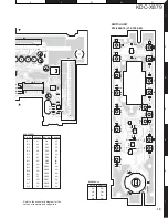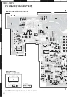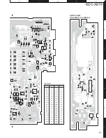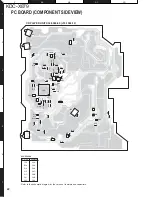
KDC-X879
11
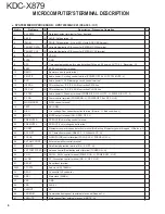
Pin No.
Pin Name
I/O
Description / Processing Operation
109,110
NC
-
NC
111
SA RST
O
Reset for spectrum analyzer (H : Reset, L : Normal)
112
3.3V VDD
-
AVR 3.3V
113
EVSS
-
GND
114~117
NC
-
NC
118~123
A21~A16
O
Address bus
124
2.5V VDD
-
AVR 2.5V
125
VSS
-
GND
126~133
A15~A8
O
Address bus
134
3.3V VDD
-
AVR 3.3V
135
EVSS
-
GND
136~143
A7~A0
O
Address bus
144
D15
I/O
External ROM data input/output terminal
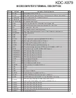
●
MECHANISM CONTROL MICROPROCESSOR : 91CW12AFG-4VF6 (X32-559 : IC1)
Pin No.
Pin Name
I/O
Description / Processing Operation
1
VREFL
I
Reference voltage input terminal
2
AVSS
-
GND for ADC
3
AVCC
-
Power supply for ADC (BU3.3V)
4
NC
O
NC (OPEN)
5
20RST
O
Reset control output terminal (for decoder) L : RESET, H : NORMAL
6
20ACK
I
Acknowledge signal input terminal (for decoder)
7
20STBY
O
Standby control (for decoder) H : STAND BY, L : NORMAL
8,9
NC
O
NC (OPEN)
10
20INT
I
Interrupt signal input terminal (for decoder)
11
FOGUP
I
Interrupt for focus gain up control signal H : Focus gain UP, L : NORMAL
12
LZM
I
0bit muting detect (Lch) L : MUTE OFF, H : MUTE ON
13
RZM
I
0bit muting detect (Rch) L : MUTE OFF, H : MUTE ON
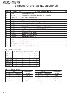
14,15
NC
O
NC
16
20CS
O
Chip select signal output terminal (for decoder)
17
20LP
O
Latch pules signal output terminal (for decoder)
18
20TXD0
I/O
Serial data signal output terminal (for decoder)
19
20RXD0
I
Serial data signal input terminal (for decoder)
20
20SCLK0
O
Serial data clock output terminal (for decoder)
21
DSPTXD1
O
Serial data signal output terminal (for DSP)
22
DSPRXD1
I
Serial data signal input terminal (for DSP)
23
DSPSCLK1
O
Serial data clock output terminal (for DSP)
24
AM0
I
Select for ROM mode H : NORMAL, L : External ROM mode
25
DVCC
-
BU3.3V
MICROCOMPUTER’S TERMINAL DESCRIPTION


