background image

11

BURNERS AND GRIDS

• 

These parts can be removed and 

cleaned with appropriate products.

• 

After cleaning, the burners and their 

flame  spreaders  must  be  well  dried 

and correctly replaced.

• 

It is very important to check that the 

burner  flame  spreader  and  the  cap 

have been correctly positioned.

• 

Failure to do so can cause serious 

problems.

• 

Check that the electrode “

S

” (figs. 3.1 - 

3.3) is always clean to ensure trouble-

free sparking.

• 

Check that the probe “

T

”  (figs.  3.1 

- 3.3) next to each burner is always 

clean to ensure the correct operation 

of the safety valves.

Both the probe and ignition plug must 

be very carefully cleaned.
Note: To avoid damage to the electric 

ignition do not use it when the burners 

are not in place.

CORRECT REPLACEMENT OF THE AUXILIARY, SEMIRAPID AND RAPID 

BURNERS

It is very important to check that the burner flame spreader “

F

” and the cap “

C

” have been 

correctly positioned (see figs. 3.1 and 3.2 ).

Failure to do so can cause serious problems.

CORRECT POSITION OF THE TRIPLE RING BURNER

The triple ring burner must be correctly positioned as indicated by the arrows in fig. 3.3.

The burner correctly positioned must not rotate (fig. 3.4).

Then position the cap “

A

” and the ring “

B

” (figs. 3.4 - 3.5).

Do not shut lid when

burner alight.

ATTENTION

Do not lower the glass lid when the 

gas burners are still hot or when 

the oven is working or still hot.
Do not lay on the glass lid hot pans 

and heavy kitchen utensils.
Dry off any liquid whitch may have 

spilt on the cover before opening it.

Models with glass lid

GLASS LID

(Optional)

Summary of Contents for KHG 601

Page 1: ...BUILT IN COOKING HOBS models KHG 601 KHG 602 Instructions for use Installation advice Before operating this hob please read these instructions carefully GB IE ...

Page 2: ...rtant Safety Precautions Recommendations Features How to Use the Cooktop Cleaning Maintenance Advice for the Installer Installation Gas Installation Electrical Installation Guarantee After Sales Service 3 4 5 6 7 10 12 13 14 16 17 21 22 23 24 ...

Page 3: ...01 KHG 602 built in cooking hobs The safety precautions and recommendations listed below are for your own safety and that of others They will also provide a means by which to make full use of the features offered by your appliance Please retain this booklet for future reference This appliance must be used only for the task it has explicitly been designed for that is for cooking foodstuffs Any othe...

Page 4: ...polystyrene foam nails packing straps etc should not be left around within easy reach of children as these may cause serious injuries Some appliances are supplied with a protective film on steel and aluminium parts This film must be removed before using the appliance IMPORTANT The use of suitable protective clothing gloves is recommended when handling or cleaning this appliance Do not attempt to m...

Page 5: ...and the hazards involved Children shall not play with the appliance Cleaning and user maintenance shall not be made by children without supervision The manufacturer declines all liability for injury to persons or damage to property caused by incorrect or improper use of the appliance WARNING During use the appliance and its accessible parts become hot they remain hot for some time after use Care s...

Page 6: ...out CAUTION If the burner is accidentally extinguished turn the gas off at the control knob and wait at least 1 minute before attempting to relight CAUTION Gas hobs produce heat and humidity in the environment in which they are installed Ensure that the cooking area is well ventilated by opening the natural ventilation grilles or by installing an extractor hood connected to an outlet duct CAUTION ...

Page 7: ...r the main gas supply line Fig 2 1 To reduce the gas flow to minimum rotate the knob further anti clockwise to point the indicator towards the small flame symbol The maximum aperture position permits rapid boiling of liquids whereas the minimum aperture position allows slower warming of food or maintaining boiling conditions of liquids Other intermediate operating adjustments can be achieved by po...

Page 8: ...2 only for model KHG 602 LIGHTING GAS BURNERS FITTED WITH SAFETY VALVE DEVICE In order to light the burner you must 1 Turn the knob in an anti clockwise direction up to the maximum aperture push in and hold the knob this will light the gas If there is no mains electrical supply bring a lighted match close to the burner 2 Wait about ten seconds after the gaslights before releasing the knob starting...

Page 9: ...d directly onto the pan support without the use of the supplied wok stand fig 2 5b IMPORTANT When using the wok stand it MUST ONLY BE PLACED over the pan support for the triple ring burner fig 2 5a Under no circumstances should the wok stand be placed under the pan supports figs 2 6a 2 6b Incorrect placement of the wok stand in this manner may impinge the flame resulting in incomplete combustion a...

Page 10: ...ype of product category However special care should be taken around the rear or the underneath of the appliance as these areas are not designed or intended to be touched and may contain sharp or rough edges that may cause injury CLEANING Stainless steel hob Spillage on the hob can usually be removed by a damp soapy cloth More obstinate stains can be removed by using a proprietary stainless steel c...

Page 11: ... do not use it when the burners are not in place CORRECT REPLACEMENT OF THE AUXILIARY SEMIRAPID AND RAPID BURNERS It is very important to check that the burner flame spreader F and the cap C have been correctly positioned see figs 3 1 and 3 2 Failure to do so can cause serious problems CORRECT POSITION OF THE TRIPLE RING BURNER The triple ring burner must be correctly positioned as indicated by th...

Page 12: ...12 S F C T Fig 3 1 Fig 3 2 A B S T Fig 3 3 Fig 3 5 Fig 3 4 ...

Page 13: ...your country and in observation of the manufacturer s instructions Always disconnect the appliance from the power supply before carrying out any maintenance operations or repairs Some appliances are supplied with a protective film on steel and aluminium parts This film must be removed before using the hob The appliance must be housed in heat resistant units These tops are designed to be embedded i...

Page 14: ...rial A 30 mm ventilation gap must be provided between the bottom of the appliance and any cabinetry draw unit thermal protection barrier or appliance If the cooktop is installed above an oven the oven shall have a cooling fan motor the two appliances shall be connected to the gas and or electrical supply with independent connections The hob must be kept no less than 200 mm away from any side wall ...

Page 15: ...G THE COOKER TOP figs 4 4 4 5 4 6 Spread the sealing material D out along the fixture hole making sure that the junctions overlap at the corners Insert the cooker top into the hole and position it correctly Adjust the position of the brackets F and R tooth C of the tabs should go into the hole Tighten screws B to block the cooker top firmly in position With a sharp cutter or trimmer knife trim the...

Page 16: ...rea will be required unless the room has a door which opens directly to the outside air in which case no permanent ventilation is required For rooms with a volume greater than 10 m3 no permanent ventilation is required Note Regardless of room size all rooms containing the appliance must have direct access to the outside air via an openable window or equivalent Where there are other fuel burning ap...

Page 17: ...Serviced by a competent person in accordance with the current editions of the following Standards Regulations or those regulations appropriate to the geographical region in which they are to be installed Gas Safety Installation Use Regulations Building Regulations British European Standards Regulations for Electrical Installation Installation and service of any gas product must be made by a suitab...

Page 18: ...actice governing such installation of gas appliances Note It is recommended that the gas connection to the appliance is installed with a flexible hose connecting tube made to BS669 Notes Flexible hoses can be used where the sited ambient temperature of the hose does not exceed 70 C These hoses must be manufactured in accordance with BS669 part 1 and be of the correct construction for the type of g...

Page 19: ...he appliance connecting pipe shall be of a sufficient size to maintain the heat output of the appliance as specified on the rating plate 1 The appliance flexible connector should not be subject to undue forces either in normal use whilst being connected or disconnected 2 The appliance flexible connector should not be subject to excessive heat by direct exposure to flue products or by contact with ...

Page 20: ...s and burners from the cooktop Using a wrench substitute the nozzle injectors J figs 5 3 5 4 with those most suitable for the kind of gas for which it is to be used The burners are conceived in such a way so as not to require the regulation of the primary air ADJUSTING OF THE MINIMUM OF THE TOP BURNERS In the minimum position the flame must have a length of about 4 mm and must remain lit even with...

Page 21: ... compliance of this obligation BURNERS Nominal Power kW Reduced Power kW LPG G30 G31 28 30 37 mbar Natural Gas G20 20 mbar Ø injector 1 100 mm Ø injector 1 100 mm Auxiliary A 1 00 0 40 50 77 Semirapid SR 1 75 0 45 66 101 Rapid R 3 00 0 75 87 129 Triple Ring TR 3 50 1 50 93 135 AIR VENT NECESSARY FOR GAS COMBUSTION 2 m3 h x kW BURNERS Air necessary for combustion m3 h Auxiliary A 2 00 Semirapid SR ...

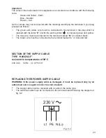
Page 22: ...hock There is a danger of electric shock if the cut off plug is inserted into any 13 amp socket outlet How to wire a 13 amp plug IMPORTANT The appliance must be installed by a qualified technician according with the current local regulations and in compliance with the manufacturer instructions Incorrect installation might cause harm and damage to people animals or objects for which the manufacture...

Page 23: ...een and yellow The blue wire must be connected to the terminal marked N or coloured black The brown wire must be connected to the terminal marked L or coloured red SECTION OF THE SUPPLY CABLE TYPE H05V2V2 F resistant to temperatures of 90 C 230 V AC 50 Hz 3 x 0 75 mm2 Replacing ther power supply cable WARNING If the power supply cable is damaged it must be replaced only by an authorised service ag...

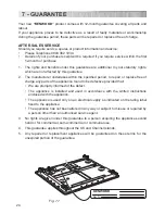
Page 24: ...es within the specified period to repair or replace free of charge any parts of the appliance found to be defective provided that We are promptly informed of the defect The appliance is installed and used in accordance with the written instructions enclosed with the appliance The appliance is used only on an electrical supply as indicated on the rating label fixed to the appliance The appliance ha...

Page 25: ...25 ...

Page 26: ...26 ...

Page 27: ...27 ...

Page 28: ...transcription errors in the present booklet The manufacturer reserves the right to make all modifications to its products deemed necessary for manufacture or commercial reasons at any moment and without prior notice without jeopardising the essential functional and safety characteristics of the appliances ...

Reviews: