background image

B64-4168-00̲00.indb   66

B64-4168-00̲00.indb   66

08.3.11   9:05:30 PM

08.3.11   9:05:30 PM

Summary of Contents for KOS-L432

Page 1: ... 58 65页 使用说明书 B64 4168 00 00 W Take the time to read through this instruction manual Familiarity with installation and operation procedures will help you obtain the best performance from your new monitor For your records Record the serial number found on the back of the unit in the spaces designated on the warranty card and in the space provided below Refer to the model and serial numbers whenever...

Page 2: ... clean soft dry cloth Applying spray cleaner directly to the unit may affect its mechanical parts Wiping the faceplate with a hard cloth or using a volatile liquid such as thinner or alcohol may scratch the surface or erases characters Screen brightness during low temperatures When the temperature of the unit falls such as during winter the liquid crystal panel s screen will become darker than usu...

Page 3: ...ction screen of Basic Operations of the A V controller s manual Operations Power Turning ON the Power Press the SRC button Turning OFF the Power Press the SRC button for at least 1 second V SEL SRC Auto Dimmer sensor Controlling of optional A V controllers is possible by touching the screen of this unit Functions which can be controlled vary depending on the A V controllers Refer to the instructio...

Page 4: ...4 English Accessories 1 1 2 1 3 1 4 1 5 1 B64 4168 00 00 indb 4 B64 4168 00 00 indb 4 08 3 11 9 04 57 PM 08 3 11 9 04 57 PM ...

Page 5: ...ot going to install the unit using the supplied monitor stand be sure to use a commercially available monitor stand Mounting holes for such a stand are located on the bottom of the monitor unit Mounting and wiring this product requires skills and experience For safety s sake leave the mounting and wiring work to professionals Do not install the unit in a spot exposed to direct sunlight or excessiv...

Page 6: ...troller Optional accessory KOS V500 MONITOR POWER Connect the wiring harness referring to the instruction manual of the connected A V controller MONITOR POWER Connect the wiring harness referring to the instruction manual of the connected A V controller A V controller Optional accessory KOS V1000 B64 4168 00 00 indb 6 B64 4168 00 00 indb 6 08 3 11 9 04 58 PM 08 3 11 9 04 58 PM ...

Page 7: ...cially available Monitor Unit Screws not supplied When installing to T Bolt compatible mounts Accessory 3 T Bolt compatible mounts commercially available Monitor Unit 3 mm or less 6 4 mm or less 12 7 mm 0 2 12 7 mm 0 2 Removing the Monitor Unit For AMPS or T Bolt compatible mounts Accessory 3 Monitor Unit B64 4168 00 00 indb 7 B64 4168 00 00 indb 7 08 3 11 9 04 59 PM 08 3 11 9 04 59 PM ...

Page 8: ... to be cut out of the headrest then carefully cut it 1 Connect Monitor and system cable Accessory 1 2 Install the monitor unit in the frame Accessory 2 Headrest Screws not supplied Monitor Unit Installation plate not supplied Paper template Accessory 5 Accessory 1 Removing the Monitor Unit For Headrest 1 Insert the removal tool Accessory 4 deeply into the slots on each side as shown Accessory 4 2 ...

Page 9: ...FT active matrix system Number of pixels 391 680 pixels 480 H 272 V RGB Effective pixels 99 99 Pixel arrangement RGB striped arrangement Back lighting LED Video section Color System of External Video Input NTSC PAL Analog RGB input 0 7 Vp p 75 Ω Specifications subject to change without notice General Operating voltage 14 4 V DC 11 16 V Current consumption 250 mA Operational temperature range 10 C ...

Page 10: ... toute trace de ce produit La pulvérisation directe de produit de nettoyage sur l appareil risque d affecter les pièces mécaniques Le fait d essuyer la façade avec un chiffon rugueux ou d utiliser un liquide volatil tel qu un solvant ou de l alcool peut égratigner la surface ou effacer les caractères Luminosité de l écran lorsque la température est basse Lorsque la température de l appareil descen...

Page 11: ...EL SRC Capteur de luminosité auto Il est possible de commander les contrôleurs A V optionnels en touchant l écran de cette unité Les fonctions pouvant êtres contrôlées varient selon le contrôleur A V Veuillez vous reporter au manuel d instructions du contrôleur A V connecté pour de plus amples informations Pour changer la source vidéo Appuyez sur la touche V SEL À chaque fois que l on appuie sur l...

Page 12: ...12 Français Accessoire 1 1 2 1 3 1 4 1 5 1 B64 4168 00 00 indb 12 B64 4168 00 00 indb 12 08 3 11 9 05 01 PM 08 3 11 9 05 01 PM ...

Page 13: ...moniteur que celui fourni assurez vous d utiliser un support de moniteur disponible dans le commerce Des trous de montage pour un tel support sont situés en bas du moniteur Le montage et le câblage de ce produit nécessitent des compétences et de l expérience Pour des raisons de sécurité laissez un professionnel effectuer le travail de montage et de câblage N installez pas l appareil dans un endroi...

Page 14: ...e optionnel KOS V500 ALIMENTATION MONITEUR Connectez le faisceau de câblage en vous reportant au manuel d instructions du contrôleur A V connecté ALIMENTATION MONITEUR Connectez le faisceau de câblage en vous reportant au manuel d instructions du contrôleur A V connecté Contrôleur A V accessoire optionnel KOS V1000 B64 4168 00 00 indb 14 B64 4168 00 00 indb 14 08 3 11 9 05 02 PM 08 3 11 9 05 02 PM...

Page 15: ...commerce Unité moniteur Vis non fournies Lors de l installation sur des systèmes de montage compatibles à boulon en T Accessoire 3 Systèmes de montage compatibles à boulon en T disponibles dans le commerce Unité moniteur 3 mm ou moins 6 4 mm ou moins 12 7 mm 0 2 12 7 mm 0 2 Retrait du moniteur Pour les systèmes de montage compatibles AMPS ou à boulon en T Accessoire 3 Unité moniteur B64 4168 00 00...

Page 16: ... à couper de l appui tête puis découpez la avec soin 1 Connectez le moniteur et le câble système Accessoire 1 2 Installez le moniteur dans le châssis Accessoire 2 Appui tête Vis non fournies Unité moniteur Plaque d installation non fournie Modèle en papier Accessoire 5 Accessoire 1 Démontage du moniteur Pour appui tête 1 Insérez profondément l outil de démontage Accessoire 4 dans les rainures situ...

Page 17: ...t Système à matrice active TFT Nombre de pixels 391 680 pixels 480 H 272 V RGB Pixels effectifs 99 99 Disposition des pixels Disposition à bande RGB Rétroéclairage DEL Section vidéo Système de couleur de l entrée vidéo externe NTSC PAL Entrée RGB analogique 0 7 Vp p 75 Ω Les spécifications sont sujettes à changements sans notification Généralités Tension de fonctionnement 14 4 V CC 11 16V Courant ...

Page 18: ...der Alkohol kann zu einem Verkratzen der Oberfläche oder zu einem Auslöschen der Beschriftung führen Bildschirmhelligkeit bei niedrigen Temperaturen Wenn die Temperatur des Gerätes fällt wie z B im Winter wird das Flüssigkristall Anzeigefeld dunkler als sonst Die normale Helligkeit kehrt zurück nachdem der Monitor einige Zeit betrieben wurde A V Controller die mit KOS L432 zu bedienen sind Stand D...

Page 19: ...s 1 Sekunde lang gedrückt V SEL SRC Auto Dimmer Sensor Die Steuerung optionaler A V Controller ist durch die Berührung des Gerätebildschirm möglich Die zu steuernden Funktionen variieren in Abhängigkeit von den A V Controllern Weitere Informationen finden Sie in der Gebrauchsanleitung des angeschlossenen A V Controllers Video Quelle umschalten Drücken Sie die V SEL Taste Bei jedem Tastendruck ände...

Page 20: ...20 Deutsch Zubehör 1 1 2 1 3 1 4 1 5 1 B64 4168 00 00 indb 20 B64 4168 00 00 indb 20 08 3 11 9 05 06 PM 08 3 11 9 05 06 PM ...

Page 21: ...s installieren stellen Sie bitte sicher dass Sie einen im Handel erhältlichen Monitorständer verwenden Die Montagelöcher für einen solchen Ständer befinden sich an der Unterseite des Monitorgerätes Die Montage sowie die Verkabelung dieses Gerätes macht besondere Fähigkeiten und Erfahrung erforderlich Überlassen Sie die Arbeiten zur Montage und Verkabelung ausgewiesenem Fachpersonal Installieren Si...

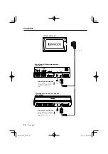
Page 22: ...Zubehör KOS V500 STROMVERSORGUNG DES MONITORS Schließen Sie den Kabelbaum gemäß der Bedienungsanleitung des angeschlossenen A V Controllers an STROMVERSORGUNG DES MONITORS Schließen Sie den Kabelbaum gemäß der Bedienungsanleitung des angeschlossenen A V Controllers an A V Controller Optionales Zubehör KOS V1000 B64 4168 00 00 indb 22 B64 4168 00 00 indb 22 08 3 11 9 05 07 PM 08 3 11 9 05 07 PM ...

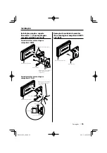
Page 23: ...ch Monitorgerät Schrauben nicht im Lieferumfang enthalten Montage an T Bolzen System Halterungen Zubehör 3 T Bolzen System Halterungen im Handel erhältlich Monitorgerät max 3 mm max 6 4 mm 12 7 mm 0 2 12 7 mm 0 2 Demontage des Monitors für AMPS oder T Bolzen System Halterungen Zubehör 3 Monitorgerät B64 4168 00 00 indb 23 B64 4168 00 00 indb 23 08 3 11 9 05 08 PM 08 3 11 9 05 08 PM ...

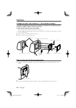
Page 24: ... Zubehör 5 und schneiden Sie sie dann vorsichtig aus 1 Verbinden Sie Monitor und Systemkabel Zubehör 1 2 Montieren Sie den Monitor im Rahmen Zubehör 2 Kopfstütze Schrauben nicht im Lieferumfang enthalten Monitorgerät Einbauplatte nicht im Lieferumfang enthalten Papierschablone Zubehör 5 Zubehör 1 Entfernen des Bildschirms für der Kopfstütze 1 Stecken Sie das Ausbauwerkzeug Zubehör 4 wie abgebildet...

Page 25: ...TFT Aktivmatrix System Anzahl der Pixel 391 680 Pixel 480 H 272 V RGB Effektive Pixel 99 99 Pixelanordnung RGB Streifenanordnung Hintergrundbeleuchtung LED Abschnitt Video Farbsystem des externen Videoeingangs NTSC PAL Analoger RGB Eingang 0 7 Vp p 75 Ω Die technischen Daten können ohne Vorankündigung geändert werden Allgemeines Betriebsspannung 14 4 V Gleichstrom 11 16 V Stromverbrauch 250 mA Bet...

Page 26: ...it kan de mechanische onderdelen beschadigen Als u voor het schoonmaken van het toestel een harde doek of een vluchtige vloeistof zoals een verdunningsmiddel of alcohol gebruikt kunnen krassen op het oppervlak worden veroorzaakt of de letters worden gewist Helderheid van het scherm bij lage temperaturen Wanneer de temperatuur van het toestel daalt bijvoorbeeld in de winter wordt het scherm van het...

Page 27: ...C toets V SEL SRC Sensor van automatische dimfunctie De bediening van optionele A V controllers is mogelijk door het scherm van deze eenheid aan te raken Welke functies kunnen worden bediend varieert afhankelijk van de specifieke A V controller Raadpleeg de instructiehandleiding bij de aangesloten A V controller voor meer informatie Omschakelen van de videobron Druk op de toets V SEL Telkens wanne...

Page 28: ...28 Nederlands Toebehoren 1 1 2 1 3 1 4 1 5 1 B64 4168 00 00 indb 28 B64 4168 00 00 indb 28 08 3 11 9 05 10 PM 08 3 11 9 05 10 PM ...

Page 29: ...et u een in de handel verkrijgbare monitorstand gebruiken Bevestigingsgaten voor een dergelijke stand bevinden zich aan de onderkant van de monitoreenheid De bevestiging en bedrading van dit product vereist vakbekwaamheid en ervaring Laat de bevestiging en bedrading om veiligheidsredenen door vaklui uitvoeren Installeer het toestel niet op plaatsen die aan direct zonlicht hitte of extreme vochtigh...

Page 30: ... KOS V500 MONITOR SPANNING Sluit de kabelboom aan Raadpleeg hierbij de instructiehandleiding bij de aangesloten A V controller voor meer informatie MONITOR SPANNING Sluit de kabelboom aan Raadpleeg hierbij de instructiehandleiding bij de aangesloten A V controller voor meer informatie A V controller optioneel toebehoren KOS V1000 B64 4168 00 00 indb 30 B64 4168 00 00 indb 30 08 3 11 9 05 11 PM 08 ...

Page 31: ...krijgbaar Monitoreenheid Schroeven niet meegeleverd Installatie aan T bout compatibele bevestigingen Toebehoren 3 T bout compatibele bevestigingen in de handel verkrijgbaar Monitoreenheid 3 mm of minder 6 4 mm of minder 12 7 mm 0 2 12 7 mm 0 2 De monitoreenheid verwijderen Voor bevestigingen die compatibel zijn met AMPS of T Bout Toebehoren 3 Monitoreenheid B64 4168 00 00 indb 31 B64 4168 00 00 in...

Page 32: ...it de hoofdsteun moet worden gesneden en verwijder dit zorgvuldig 1 Sluit de monitor en systeemkabel aan toebehoren 1 2 Installeer de monitoreenheid in het frame toebehoren 2 Hoofdsteun Schroeven niet meegeleverd Monitoreenheid Installatieplaat niet meegeleverd Papierpatroon toebehoren 5 Toebehoren 1 Verwijderen van de monitoreenheid Voor hoofdsteun 1 Steek het verwijderstaafje toebehoren 4 diep i...

Page 33: ...TFT actief matrix systeem Aantal pixels 391 680 pixels 480 H 272 V RGB Effectieve pixels 99 99 Pixelopstelling RGB striped opstelling Achtergrondlicht LED Videogedeelte Kleursysteem of externe video ingang NTSC PAL Analoge RGB ingang 0 7 Vp p 75 Ω Technische gegevens zijn zonder voorafgaande kennisgeving wijzigbaar Algemeen Bedrijfsspanning 14 4 V gelijkstroom 11 16V Stroomverbruik 250 mA Bedrijfs...

Page 34: ...nuovo con un panno asciutto e pulito L uso di un detergente spray direttamente sull unità può danneggiare le parti meccaniche L uso di un panno non morbido o di un liquido volatile come un solvente o dell alcol può graffiare la superficie o cancellare i caratteri Luminosità dello schermo a basse temperature Quando la temperatura dell unità si abbassa come ad esempio durante l inverno lo schermo de...

Page 35: ...er almeno 1 secondo V SEL SRC Sensore Dimmer automatico I controller A V opzionali possono essere controllati sfiorando la schermata di questa unità Le funzioni che possono essere controllate variano a seconda dei controller A V Per ulteriori informazioni fare riferimento al Manuale di istruzioni del controller A V collegato Selezione della sorgente video Premete il tasto V SEL Ogni volta che vien...

Page 36: ...36 Italiano Accessori 1 1 2 1 3 1 4 1 5 1 B64 4168 00 00 indb 36 B64 4168 00 00 indb 36 08 3 11 9 05 14 PM 08 3 11 9 05 14 PM ...

Page 37: ...assicuratevi di utilizzare un sostegno per monitor disponibile sul mercato I fori di montaggio per tale sostegno sono ubicati sulla parte inferiore dell unità monitor Il montaggio e il cablaggio di questo prodotto richiedono conoscenze specifiche ed esperienza Per motivi di sicurezza affidate il montaggio e il cablaggio a dei professionisti Non installate l apparecchio in un luogo esposto a luce s...

Page 38: ...troller A V accessorio opzionale KOS V500 ACCENSIONE MONITOR Collegare il cablaggio seguendo il manuale di istruzioni del controller A V collegato ACCENSIONE MONITOR Collegare il cablaggio seguendo il manuale di istruzioni del controller A V collegato Controller A V accessorio opzionale KOS V1000 B64 4168 00 00 indb 38 B64 4168 00 00 indb 38 08 3 11 9 05 15 PM 08 3 11 9 05 15 PM ...

Page 39: ...o Unità monitor Viti non fornite Durante l installazione di montaggi compatibili con Bulloni a T Accessorio 3 Montaggi compatibili con Bulloni a T disponibili in commercio Unità monitor 3 mm o inferiore 6 4 mm o inferiore 12 7 mm 0 2 12 7 mm 0 2 Rimozione dell unità del monitor Per montaggi compatibili con AMPS o Bulloni a T Accessorio 3 Unità monitor B64 4168 00 00 indb 39 B64 4168 00 00 indb 39 ...

Page 40: ... poggiatesta da ritagliare e poi tagliarla con attenzione 1 Collegare il cavo del monitor e del sistema Accessorio 1 2 Installare l unità del monitor nel telaio Accessorio 2 Poggiatesta Viti non fornite Unità monitor Piastra di installazione non fornita Modello in carta Accessorio 5 Accessorio 1 Rimozione del monitor Per poggiatesta 1 Inserite l apposito attrezzo per la rimozione Accessorio 4 nell...

Page 41: ...CD modo VA Sistema di azionamento Sistema a matrice attiva TFT Numero di pixel 391 680 pixel 480 H 272 V RGB Pixel effettivi 99 99 Disposizione dei pixel Disposizione a strisce RGB Retroilluminazione LED Sezione video Sistema colori dell ingresso video esterno NTSC PAL Ingresso analogico RGB 0 7 Vp p 75 Ω Specifiche soggette a cambiamenti senza preavviso Generale Voltaggio operativo 14 4 V CC 11 1...

Page 42: ... la unidad puede que afecte a sus partes mecánicas Si se limpia la placa frontal con un paño duro o utilizando líquido volátil tal como disolvente o alcohol puede que se raye la superficie o que se borren algunos caracteres Brillo de la pantalla durante temperaturas bajas Cuando la temperatura de la unidad desciende como por ejemplo durante el invierno la pantalla del panel de cristal se oscurecer...

Page 43: ...o V SEL SRC Sensor de atenuación automática El control de controladores de A V opcionales es posible con sólo tocar la pantalla de esta unidad Las funciones que se pueden controlar varían dependiendo de los controladores de A V Consulte el manual de instrucciones del controlador de A V conectado para obtener más información Cambio de la fuente de vídeo Pulse el botón V SEL Cada vez que se pulsa el...

Page 44: ...44 Español Accesorios 1 1 2 1 3 1 4 1 5 1 B64 4168 00 00 indb 44 B64 4168 00 00 indb 44 08 3 11 9 05 18 PM 08 3 11 9 05 18 PM ...

Page 45: ...oporte de monitor de los disponibles en el comercio los agujeros de montaje para tales tipos de soportes están localizados en la parte inferior del monitor La instalación y cableado de este producto requiere de habilidad y experiencia Por motivos de seguridad deja la labor de instalación y montaje en manos de profesionales No instale la unidad en un sitio expuesto a la luz directa del sol o excesi...

Page 46: ...0 ALIMENTACIÓN DEL MONITOR Conecte el mazo de conductores al que hace referencia el manual de instrucciones del controlador de A V conectado ALIMENTACIÓN DEL MONITOR Conecte el mazo de conductores al que hace referencia el manual de instrucciones del controlador de A V conectado Controlador de A V accesorio opcional KOS V1000 B64 4168 00 00 indb 46 B64 4168 00 00 indb 46 08 3 11 9 05 19 PM 08 3 11...

Page 47: ... disponible Monitor Tornillos no suministrados Al instalar en un montaje compatible con Tornillo T Accesorio 3 Montajes compatibles con Tornillo T comercialmente disponible Monitor 3 mm o menos 6 4 mm o menos 12 7 mm 0 2 12 7 mm 0 2 Remoción de la unidad del monitor Para montaje compatible con AMPS o Tornillo T Accesorio 3 Monitor B64 4168 00 00 indb 47 B64 4168 00 00 indb 47 08 3 11 9 05 20 PM 08...

Page 48: ... la zona que se va a retirar del reposacabezas y córtela cuidadosamente 1 Conecte el cable del sistema al monitor Accesorio 1 2 Instale la unidad de monitor en la estructura Accesorio 2 Reposacabezas Tornillos no suministrados Monitor Placa de instalación no suministrada Plantilla de papel Accesorio 5 Accesorio 1 Extracción del monitor Para reposacabezas 1 Inserte la herramienta de extracción Acce...

Page 49: ...amiento Sistema de matriz activa TFT Número de píxeles 391 680 píxeles 480 H 272 V RGB Píxeles efectivos 99 99 Disposición de píxeles Disposición de bandas RGB Iluminación de fondo LED Sección de vídeo Sistema de color de la entrada externa de vídeo NTSC PAL Entrada RGB analógica 0 7 Vp p 75 Ω Las especificaciones se encuentran sujetas a cambios sin previo aviso General Voltaje de funcionamiento 1...

Page 50: ...te neutro Aplicar um produto de limpeza directamente na unidade poderá afectar as suas peças mecânicas Limpar o painel com um pano áspero ou usar um líquido volátil tal como um diluente ou álcool poderá riscar a superfície ou apagar caracteres Brilho do ecrã a baixas temperaturas Quando a temperatura ambiente em redor da unidade baixar tal como no Inverno o ecrã do painel de cristal líquido tornar...

Page 51: ...pelo menos 1 segundo V SEL SRC Sensor redutor de iluminação automático É possível controlar os controladores A V opcionais tocando no ecrã desta unidade As funções que podem ser controladas variam dependendo dos controladores A V Consulte o manual de instruções do controlador A V ligado para mais informações Comuta a fonte vídeo Pressione o botão V SEL Cada vez que o botão é pressionado a fonte ví...

Page 52: ...52 Português Acessórios 1 1 2 1 3 1 4 1 5 1 B64 4168 00 00 indb 52 B64 4168 00 00 indb 52 08 3 11 9 05 23 PM 08 3 11 9 05 23 PM ...

Page 53: ...um suporte de monitor disponível no mercado Os orifícios de montagem para tal suporte estão localizados no fundo da unidade do monitor A instalação e ligação deste aparelho requerem conhecimentos e experiência Para sua segurança deixe o trabalho de montagem e ligação ser feito por profissionais Não instalar o aparelho num local exposto à luz solar directa ou calor e humidade excessivos Evitar tamb...

Page 54: ...ador A V Acessório opcional KOS V500 ALIMENTAÇÃO DO MONITOR Ligue a cablagem consultando a manual de instruções do controlador A V que está ligado ALIMENTAÇÃO DO MONITOR Ligue a cablagem consultando a manual de instruções do controlador A V que está ligado Controlador A V Acessório opcional KOS V1000 B64 4168 00 00 indb 54 B64 4168 00 00 indb 54 08 3 11 9 05 23 PM 08 3 11 9 05 23 PM ...

Page 55: ...Unidade de Monitor Parafusos não fornecidos Quando instalar em montagens compatíveis T Bolt Acessório 3 Montagens compatíveis T Bolt disponíveis no comércio Unidade de Monitor 3 mm ou menos 6 4 mm ou menos 12 7 mm 0 2 12 7 mm 0 2 Remoção da unidade do monitor Para montagens compatíveis AMPS ou T Bolt Acessório 3 Unidade de Monitor B64 4168 00 00 indb 55 B64 4168 00 00 indb 55 08 3 11 9 05 24 PM 08...

Page 56: ...o encosto de cabeça e depois corte o cuidadosamente 1 Ligue o monitor e o cabo do sistema Acessório 1 2 Instale o monitor no chassi Acessório 2 Encosto da cabeça Parafusos não fornecidos Unidade de Monitor Placa de instalação não fornecida Molde de papel Acessório 5 Acessório 1 Remoção do monitor Para encosto da cabeça 1 Introduza a ferramenta de remoção Acessório 4 profundamente nas aberturas de ...

Page 57: ...tema de impulso Sistema de comando de matriz activa TFT Número de pixels 391 680 pixels 480 H 272 V RGB Pixels efectivos 99 99 Disposição de pixels Disposição em faixas RGB Contraluz LED Secção vídeo Sistema de cor da entrada de vídeo externa NTSC PAL Entrada RGB analógica 0 7 Vp p 75 Ω As especificações podem ser alteradas sem prévia notificação Geral Tensão de operação 14 4 V CC 11 16 V Consumo ...

Page 58: ...地说明如何进行控制的说明例子 因 此 出现在插图中的显示屏幕可能与实际出现在 装置上的显示不同 并且有些显示屏幕的插图可 能在实际操作中无法实现 因此 出现在插图中 的显示屏幕可能与实际出现在装置上的显示不 同 并且有些显示屏幕的插图可能在实际操作中 无法实现 装置的保养 如果本机的面板被弄脏 请使用硅布等干燥的软布 擦拭清洁 如果面板很脏 请蘸中性清洁剂擦拭污垢 然后擦 去清洁剂 对本机直接喷洒清洁剂将可能使得机械部件受到影响 使用硬质的布或者使用诸如稀释剂或酒精等挥发性溶剂 擦拭面板将划伤表面或者将字符擦掉 温度较低时的屏幕亮度 诸如在冬季等 当本机的环境温度较低时 液晶屏 幕将比通常暗淡 当显示器使用了一段时间后 可 恢复正常的亮度 可由KOS L432控制的A V控制器 截止至 2007年12月 KOS V500 KOS V1000 B64 4168 00 00 indb 58 B...

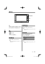
Page 59: ...接通电源 按下 SRC 按钮 切断电源 按下 SRC 按钮1秒钟以上 V SEL SRC 自动调光传感器 触按操作本机的屏幕可以控制选购的A V控制器 不同的A V控制器可以控制的功能不同 有关详细 内容 请参照连接的A V控制器的使用说明书 切换影像信号源 按下 V SEL 按钮 每次按下该按钮 影像信号源即切换 请参照A V控制器使用说明书 基本操作 的 切换 影像信号源 切换音响信号源 按下 SRC 按钮 每次按下该按钮 音响信号源即切换 请参照A V控制器使用说明书 基本操作 的 切换 音响信号源 B64 4168 00 00 indb 59 B64 4168 00 00 indb 59 08 3 11 9 05 26 PM 08 3 11 9 05 26 PM ...

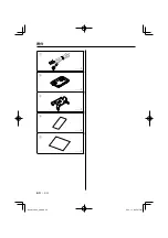
Page 60: ...60 中文 附件 1 1 2 1 3 1 4 1 5 1 B64 4168 00 00 indb 60 B64 4168 00 00 indb 60 08 3 11 9 05 27 PM 08 3 11 9 05 27 PM ...

Page 61: ... 或受 潮气或高温影响的位置 在这些位置安装可能会引起显示器的变形 如果您不打算使用随机附带的显示器座架安装本装置 请务必使用可从商店购买的座架 这种座架的安装孔位 于显示器的底部 本产品的安装和接线需要由具备经验和技能的人员完 成 为了保证安全 请专业人员完成安装和接线作业 请勿将本装置安装在曝露于直射阳光 高温或高湿 水 可能飞溅的或有灰尘的地方 并且避免灰尘过多或水可 能飞溅的地方 安装时 请务必使用所附的螺丝 请务必使用随机提供 的螺丝 如使用其他的螺丝 可能会造成装置的故障 保险丝烧断时 应检查导线等有无短路 然后更换规定 容量相同的保险丝 请勿将未连接的导线和端子触碰已连接电源的汽车金属 部位等 另外 为了防止短路事故 请不要拆卸附在未 连接的导线和端子上的外罩 在完成安装后 检查汽车的制动灯 转向灯 雨刷等是 否工作正常 请用乙烯带等绝缘物包覆未连接的导线 仔细擦净安装表面的...

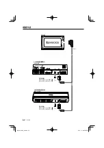
Page 62: ...DEO VIDEO AV OUT 2 AV OUT 1 R CAM V IN MONITOR POWER MONITOR I F POWER 附件1 显示器 A V控制器 选购附件 KOS V500 显示器电源 请参照连接的A V控制器 使用说明书连接导线束 显示器电源 请参照连接的A V控制器 使用说明书连接导线束 A V控制器 选购附件 KOS V1000 B64 4168 00 00 indb 62 B64 4168 00 00 indb 62 08 3 11 9 05 28 PM 08 3 11 9 05 28 PM ...

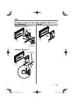
Page 63: ...容AMPS的支架上时 附件3 兼容AMPS的支架 可以在市场上购买 显示器 螺丝 不随机提供 当安装在兼容T 螺栓的支架上时 附件3 兼容T 螺栓的支架 可以在市场上购买 显示器 不超过3mm 不超过6 4 mm 12 7 mm 0 2 12 7 mm 0 2 取下显示器装置 对于兼容AMPS或T 螺 栓的支架 附件3 显示器 B64 4168 00 00 indb 63 B64 4168 00 00 indb 63 08 3 11 9 05 28 PM 08 3 11 9 05 28 PM ...

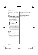
Page 64: ...装向头靠之前 首先完成需要的外部连接 附件1 使用随机提供的纸样 附件5 画出头靠上的挖除范围 然后小心挖除 1 连接显示器和系统导线 附件1 2 将显示器安装到框架中 附件2 头靠 螺丝 不随机提供 显示器 安装板 不随机提供 纸样 附件5 附件1 显示器装置的拆除方法 对于头靠 1 如图所示 将拆卸工具 附件4 全部插入两侧的插槽 附件4 2 用手将显示器装置向外拉出 并且注意防止落下 附件2 B64 4168 00 00 indb 64 B64 4168 00 00 indb 64 08 3 11 9 05 29 PM 08 3 11 9 05 29 PM ...

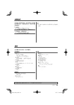
Page 65: ... TFT有效矩阵系统 像素数 391 680像素 480 H 272 V RGB 有效像素 99 99 像素排列 RGB带状排列 背景照明 LED 视频部分 外部视频输入的彩色系统 NTSC PAL 模拟RGB输入 0 7 Vp p 75 Ω 技术规格可能有所变更 恕无事前通知 共同 电源电压 14 4V DC 11V 16V 消费电流 250 mA 工作环境温度范围 10 至 60 保存环境温度范围 20 至 70 外形尺寸 W H D 125 75 18 5 mm 4 15 16 2 15 16 6 8 英寸 重量 150 g 0 33 磅 规格 尽管液晶面板的有效像素为99 99 以上 0 01 的像素可能不能正常发亮 有关操作中的故障排除 请参照连接的A V控制器使用 说明书 B64 4168 00 00 indb 65 B64 4168 00 00 indb 65 08 3 11...

Page 66: ...B64 4168 00 00 indb 66 B64 4168 00 00 indb 66 08 3 11 9 05 30 PM 08 3 11 9 05 30 PM ...

Page 67: ...this equipment does cause harmful interference to radio or television reception which can be determined by turning the equipment off and on the user is encouraged to try to correct the interference by one or more of the following measures Reorient or relocate the receiving antenna Increase the separation between the equipment and receiver Connect the equipment into an outlet on a circuit different...

Page 68: ...B64 4168 00 00 indb 68 B64 4168 00 00 indb 68 08 3 11 9 05 31 PM 08 3 11 9 05 31 PM ...

Reviews: