4
RXD-M909/LS-M909
How to Reset Parental Lock
1. Press the [SETUP] key to display the Setup menu.
2. Input the 6-digit number “210499” and the pass-word is
cleared.
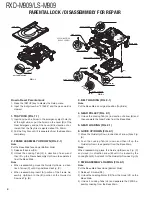
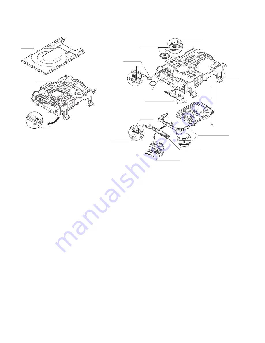
1. TRAY DISC (FIG. 1-1)
1) Insert and push a Driver in the emergency eject hole (A)
at the right side, or put the Driver on the Lever (B) of the
Gear Emergency and pull the Lever (B) in direction of ar-
row so that the Tray Disc is ejected about 15~20mm.
2) Pull the Tray Disc until it is separated from the Base Main
completely.
2. FRAME ASSEMBLY UP/DOWN (FIG. 2-1)
Note
Put the Base Main face down (Bottom Side)
1) Release the screw (S4)
2) Unlock the Locking Tab (L3) in direction of arrow and
then lift up the Frame Assembly Up/Down to separate it
from the Base Main.
Note
• When reassembling move the Guide Up/Down in direc-
tion of arrow (C) until it is positioned as Fig. (C).
• When reassembling insert (A) portion of the Frame As-
sembly Up/Down in the (B) portion of the Guide Up/
Down as Fig. (B)
3. BELT LOADING (FIG. 2-1)
Note
Put the Base Main on original position (Top Side)
4. GEAR PULLEY (FIG. 2-1)
1) Unlock the Locking Tab (L4) in direction of arrow (B) and
then separate the Gear Pulley from the Base Main.
5. GEAR LOADING (FIG. 2-1)
6. GUIDE UP/DOWN (FIG. 2-1)
1) Move the Guide Up/Down in direction of arrow (A) as Fig.
(A)
2) Push the Locking Tab (L5) down and then lift up the
Guide Up/Down to separate it from the Base Main.
Note
When reassembling place the Guide Up/Down as Fig. (C)
and move it in direction arrow (B) until it is locked by the
Locking Tab (L5). And con
fi
rm the Guide Up/Down as Fig. (A)
7. PWB ASSEMBLY LOADING (FIG. 2-1)
Note
Put the Base Main face down (Bottom Side)
1) Release 1 Screws (S5)
2) Unlock the Loading Motor (C2) from the Hook (H1) on the
Base Main.
3) Unlock 2 Locking Tabs (L6) and separate the PWB As-
sembly Loading from the Base Main.
GEAR LOADING
GEAR PULLEY
BELT LOADING
PWB ASSEMBLY LOADING
BASE MAIN
GUIDE UP/DOWN
GUIDE UP/DOWN
GUIDE UP/DOWN
UP/DOWN FRAME ASSEMBLY
GUIDE UP/DOWN
BASE MAIN
(L6)
(L4)
(L6)
(H1)
(C2)
(S5)
(S4)
(S4)
(A)
(A)
(B)
(B)
(C)
(L5)
FIG. (A)
FIG. (B)
FIG. (C)
(A)
(B)
FIG. 2-1
SCREW INSERTION
TORGUE CONTROL
TRAY DISC
BASE MAIN
LEVER
BASE MAIN
BOTTOM SIDE VIEW
FIG. 1-1
PARENTAL LOCK / DISASSEMMBLY FOR REPAIR

