NX-720
46
●
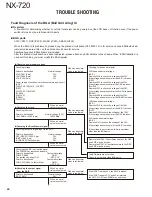
When an error display appears on the LCD.
The LCD displays “ ERROR 1”.
An error occurs when the ASIC internal RAM reads
or writes. The ASIC may be broken.
The LCD displays “ ERROR 2”.
An error occurs when the DSP internal RAM reads
or writes. The DSP may be broken.
The LCD displays “ ERROR 3”.
An error occurs when the SRAM reads or writes.
The SRAM may be broken.
●
Checking the signal output from
the ASIC by software control
●
Panel control (TX-RX unit: AVR)
It is unlikely that the BGA parts are broken.
Points to be checked
Normal voltage
50C CN412
5.0V
Points to be checked
Normal voltage
SBC R407
3.3V
Points to be checked
Normal voltage
80C CN414
8.0V
If the SBC is 3.3V, when the voltage value of 80C and
50C is abnormal, the BGA parts are not broken.
Remove R407. If the ASIC side is 0V,
the ASIC/FLASH/SRAM may be broken.
●
Panel control (Display unit)
Checking the Control signal
Points to be checked
Normal voltage
LCDCE CN514 (20 pin) 5.0V or 0V
LCDCL CN514 (21 pin)
LCDDI CN514 (19 pin)
If Display unit is removed and a waveform becomes
normal, the BGA parts are not broken.
When a waveform is abnormal, the IC511 may be
broken.
Points to be checked
Normal voltage
/DRST R524
3.3V
If the /DRST is 0V, the ASIC/FLASH/SRAM are broken.
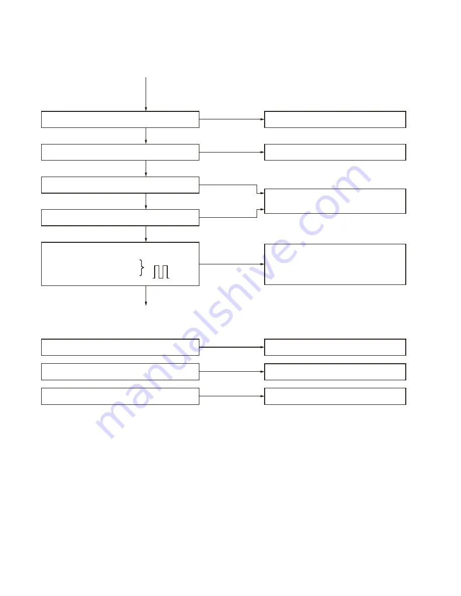
When a normal
value is confirmed.
When a normal
value is confirmed.
When a normal
value is confirmed.
When a normal
value is confirmed.
When a normal
value is confirmed.
When a normal
value is confirmed.
When an abnormal
value is confirmed.
When an abnormal
value is confirmed.
When an abnormal
value is confirmed.
When an abnormal
value is confirmed.
When an abnormal
value is confirmed.
TROUBLE SHOOTING
Summary of Contents for NEXEDGE NX-720
Page 122: ...NX 720 ...

