


2
REPEATER OPERATION
Note: Please consult your dealer for programming the repeater.
When power is applied to the unit, the
POWER indicator lights:
• Green when using the main DC jack.
Rotate the
VOLUME control to adjust the audio.
The
BUSY indicator lights green while receiving a signal and the
TX indicator lights red while transmitting.
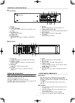
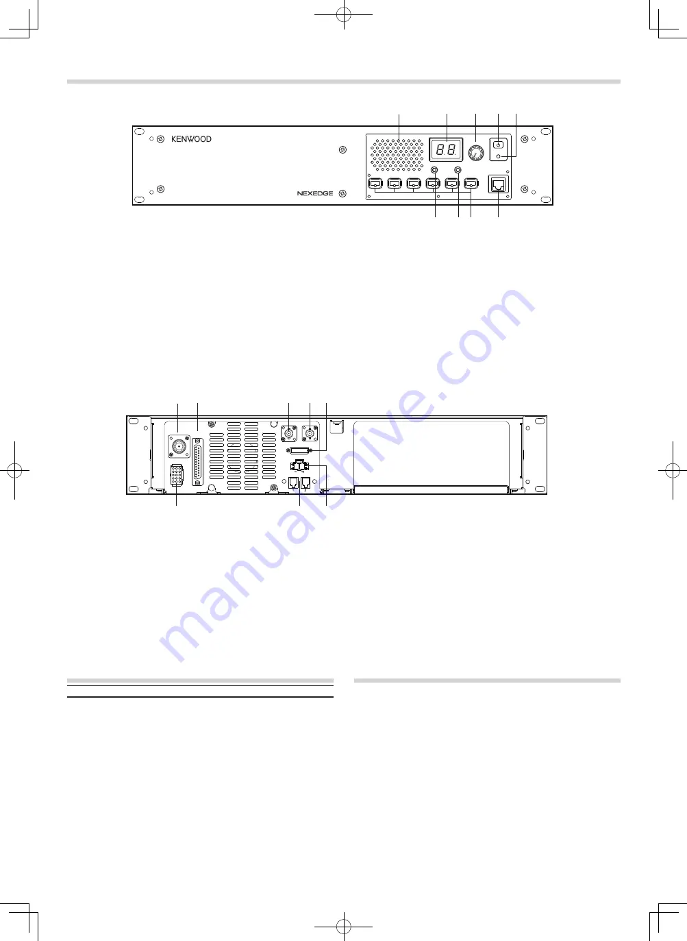
■
Rear Panel
a
TX OUT jack
Connect a TX antenna or a duplexer to this receptacle.
b
CONTROL I/O jack
Connect a repeater controller or a remote panel to this
DB-25 interface.
c
REF IN jack
Connect to a 10 MHz external oscillator.
d
RX IN jack
Connect an RX antenna or a duplexer to this BNC
receptacle.
CONTROLS AND FUNCTIONS
■
Front Panel
e
FUSE
Insert 15 A blade fuse into this fuse holder.
f
DC 13.6V jack
Connect a 13.6 V DC power supply to this jack.
g
N SYNC 1 / 2 jack
This jack is currently not used . You can connect another
repeater here for future functions.
h
TEST/SPKR jack
Test input/output jack. Connect an external speaker to
this jack.
TRANSCEIVER OPERATION
■
Receive
Adjust the volume to your desired level. You may need to
readjust the volume if you are having interference while
receiving a message from your dispatcher or another member
in your fleet.
The
BUSY indicator lights green while a signal is being
received.
■
Transmit
1 Listen to the channel before transmitting, to make sure it
is not being used.
2 Press the microphone PTT switch, then speak in your
normal speaking voice.
The
TX indicator lights red while transmitting.
3 When you finish speaking, release the PTT switch.
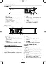
a
Speaker
b
CH/STATUS Display
Two 7-segment digits display the channel number, name,
or status.
c
VOLUME control
Rotate to adjust the audio.
d
POWER switch
e
POWER indicator
Lights green when power is supplied to the
DC 13.6V
jack.
f
MIC jack
Connect a microphone to this 8-pin modular jack.
g
Programmable Function keys
Press these keys to activate their programmable functions.
h
BUSY indicator
Lights green while a signal is being received.
i
TX indicator
Lights red while transmitting.
CH/STATUS
VOLUME
BUSY
TX
POWER
MIC
a
b
d e
f
g
h
i
c
FUSE
N S Y N C
D C 1 3 . 6 V
REF
IN
RX
IN
TX OUT
CONTROL
I / O
TEST/SPKR
a
b
d e
f
g
h
c
Summary of Contents for Nexedge NXR-710-K
Page 8: ......


