1-38 (No.RA020<Rev.002>)
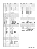
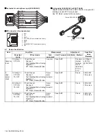
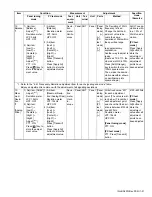
P25 Phase1 signaling
P25 Phase2 signaling
NXDN Mode signaling
RAN: Radio Access Number
PN9: Pseudo-Random Pattern
No.7, 9 Item: PC test mode only
4.3
Panel Tuning Mode
4.3.1 Transceiver tuning (To enter tuning mode)
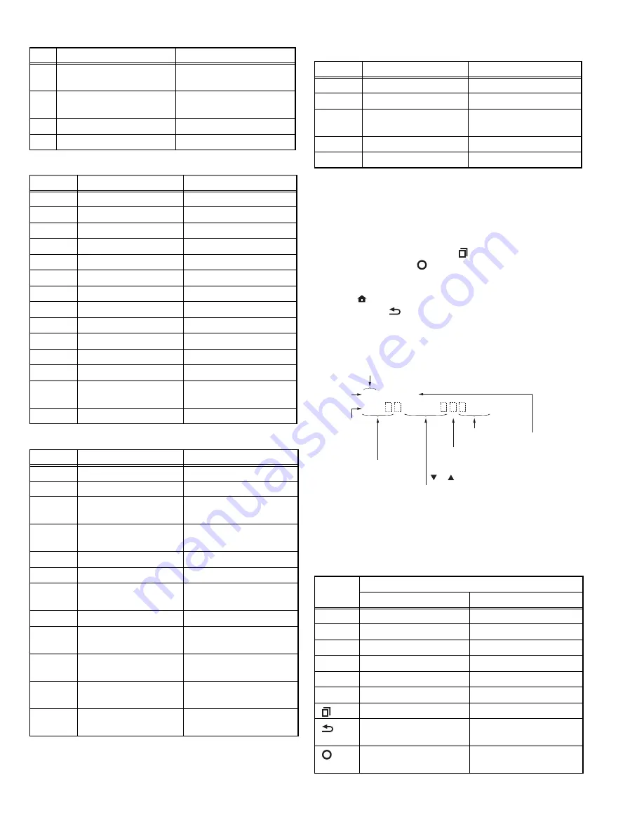
To enter tuning mode, press the [ ] key while the transceiver
is in test mode. Use the [ ] key to write tuning data through tun-
ing modes, and the [
]/[
] key to adjust tuning requirements
(1 to 4096 appears on the LCD).
Use the [ ] key to select the adjustment item through tuning
modes. Use the [
] key to adjust 4, 6 or 8 reference level ad-
justments, and use the [
] key to switch between Wide5k/
Wide4k/Narrow.
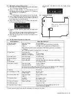
• LCD display in panel tuning mode
4.3.2 Key operation
13
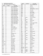
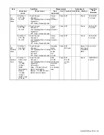
Single Tone Decode
(979.9Hz)
Single Tone Encode
(979.9Hz)
14
None
Single Tone Encode
(1000Hz)
15
None
MSK PN9
16
MSK Decode
MSK Encode
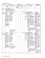
No.
RX
TX
1
NAC 293
NAC 293
2
NAC 023
NAC 023
3
NAC 5EA
NAC 5EA
4
None
PN9
5
NAC 293
Symbol Rate Pattern
6
NAC 293
1/3 Deviation Pattern
7
NAC 293
0 Continuous Pattern
8
NAC 293
Fidelity Pattern
9
None
FSW+PN9
10
None
1011Hz Tone Test Pattern
11
Tone Pattern
1011Hz Tone Test Pattern
12
Silence Pattern
Silence Pattern
13
Audio Test Pattern
Audio Test Pat-
tern
14
Vocoder Loop
None
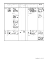
No.
RX
TX
1
STTP-OB-1031-0
STTP-IB1031-1+Audio
2
None
PN9 Phase2
3
STTP-OB-1031-1
Symbol Rate Pattern
Phase2
4
STTP-OB-1031-1
1/3 Deviation Pattern
Phase2
5
STTP-OB-1031-1
0 Continuous Pattern
6
STTP-OB-1031-1
0 Burst Pattern
7
STTP-OB-1031
Symmetrical
STTP-IB1031-1
8
Tone Pattern (Half rate) STTP-IB1031-1
9
Silence Pattern
(Half Rate)
STP-IB-1 +
Silence Pattern (Half Rate)
10
Audio Test Pattern
(Half Rate)
STTP-IB1031-1 + Audio
Test Pattern (Half Rate)
11
Codec Loop
STTP-IB1031-1 + Codec
Loop
12
Vocoder Loop
(Half Rate)
STTP-IB1031-1 +
Vocoder Loop (Half Rate)
No.
RX
TX
No.
RX
TX
1
RAN1
RAN1
2
None
PN9
3
RAN1
Maximum Deviation
Pattern
7
FSW + PN9
FSW + PN9
9
Tone Pattern (1031Hz) Tone Pattern (1031Hz)
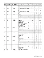
Key
Function
Push
Hold (1 second)
[+]
Volume up
Continuation up
[-]
Volume down
Continuation down
[
]
Adjustment value up
Continuation up
[
]
Adjustment value down
Continuation down
[
]
Auto adjustment start
-
[
]
Wide/Narrow/P25/NXDN -
[ ]
Shift to panel test mode
-
[ ]
To enter 5,9 or 17 refer-
ence level adjustments
-
[ ]
Writes the adjustment
value
-
An RAST 256
2.6
CV voltage, AD value, etc
Sub LCD
display
Low1
Adjustment point
Main LCD
display
Adjustment value
(1~4096)
Proper value guide
(When the frequency
adjustment is necessary,
or is displayed.)
Adjustment item
An: Analog narrow mode
As: Analog wide 4k mode *1
Aw: Analog wide mode
P1: P25 Phase1 mode
P2: P25 Phase2 mode
Nn: NXDN narrow mode
Nv: NXDN very narrow mode
Low1
Low2
Low3
Center1
Center2
Center3
High1
High2
High3
*1: Wide 4k is displayed only when the PC test mode is used. However, it aims
at production for factory, or a operation verification of the transceiver. It is
not necessary in operation of the transceiver to adjust.
Summary of Contents for NX-5700
Page 106: ...MEMO ...
Page 137: ...MEMO ...

