(No.RA020<Rev.002>)1-89
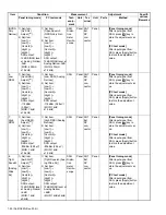
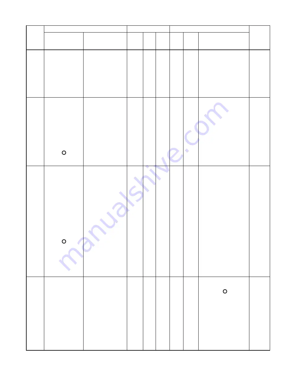
4.20 Receiver Section
Item
Condition
Measurement
Adjustment
Specifi-
cations
/Remarks
Panel tuning mode
PC test mode
Test-
equip-
ment
Unit
Ter-
minal
Unit
Parts
Method
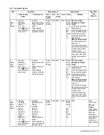
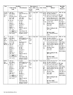
1.
AF level
setting
[Panel test mode]
1) CH-Sig: 1-1
SSG output:
-47dBm (1mV)
(MOD: 1kHz/
±1.5kHz)
1) Test Channel
Channel: 1
Test Signaling
Mode: Analog
Signaling: 1
SSG output:
-47dBm (1mV)
(MOD:1kHz/
±1.5kHz)
SSG
DVM
AF VM
Dummy
load
Panel ANT
Ext.
SP
con-
nector
Panel [Panel
tuning
mode]
[+], [-]
[PC
test
mode]
[
←
],
[
→
]
Volume Up/Down knob to
obtain 1.41V AF output.
(0.5W @ 4
Ω
load)
1.41V
±0.1V
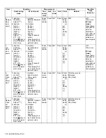
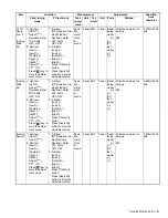
2. Sen-
sitivity 2
1) Adj item:
[An SENS2]
Adjust:[***]
2) Adj item:
[Low1]
→
[Low3]
→
[Center2]
→
[High1]
→
[High3]
Adjust:[***]
Press [ ] key to
store the adjust-
ment value.
1) Adj item:
[Sensitivity 2]
2) Adj item:
[Low1], [Low3],
[Center2], [High1],
[High3]
Press [Apply All]
button to store the
adjustment value.
SSG
AF VM
Dummy
load
Panel ANT
Ext.
SP
con-
nector
Panel [Panel
tuning
mode]
[
],
[
]
[PC
test
mode]
[
←
],
[
→
]
Write the value as follow-
ings.
[Low1]: 80 (Fixed)
[Low3]: 85 (Fixed))
[Center2]: 110 (Fixed)
[High1]: 135 (Fixed)
[High3]: 160 (Fixed)
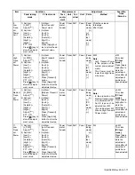
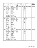
3. Sen-
sitivity 1
1) Adj item:
[An SENS1]
Adjust:[***]
2) Adj item:
[Low1]
→
[Low3]
→
[Center2]
→
[High1]
→
[High3]
SSG output:
-100dBm (2.2
μ
V)
(MOD: 1kHz/
±1.5kHz)
Adjust:[***]
Press [ ] key to
store the adjust-
ment value.
1) Adj item:
[Sensitivity 1]
2) Adj item:
[Low1], [Low3],
[Center2], [High1],
[High3]
SSG output:
-100dBm (2.2
μ
V)
(MOD: 1kHz/
±1.5kHz)
Press [Apply All]
button to store the
adjustment value.
SSG
AF VM
Dummy
load
Panel ANT
Ext.
SP
con-
nector
Panel [Panel
tuning
mode]
[
],
[
]
[PC
test
mode]
[
←
],
[
→
]
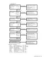
1) The sub LCD display
shows the RSSI value.
Change the adjustment
value to get maximum
RSSI value.
2) Store the adjustment
value.
Note:
In the PC test mode, you
can also perform the Au-
tomatic adjustment.
When the Automatic ad-
justment is performed in
the PC test mode, a
RSSI value is updated
by press [Apply All] but-
ton.
Press [Apply All] button
after the adjustment and
check the state of the
newest RSSI.
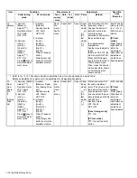
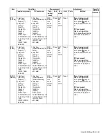
4. RSSI
refer-
ence
1) Adj item:
[An RRSSI]
Adjust:[***]
2) Adj item:
[Low1]
→
[Low3]
→
[Center2]
→
[High1]
→
[High3]
SSG output:
12dB SINAD level
-3dB
(MOD:
1kHz/±1.5kHz)
1) Adj item:
[RSSI Reference
(Analog Narrow)]
2) Adj item:
[Low1]
→
[Low3]
→
[Center2]
→
[High1]
→
[High3]
SSG output:
12dB SINAD level
-3dB
(MOD:
1kHz/±1.5kHz)
SSG
Distor-
tion
meter
Oscillo-
scope
Panel ANT
Ext.
SP
con-
nector
Panel
[Panel tuning mode]
After input signal from
SSG, press [ ] key to
store the adjustment val-
ue.
[PC test mode]
After input signal from
SSG, press [Apply] button
to store the adjustment
value.
Summary of Contents for NX-5700
Page 106: ...MEMO ...
Page 137: ...MEMO ...

