1-36 (No.RA020<Rev.002>)
SECTION 4
ADJUSTMENT
4.1
F,K TYPE Controls
4.1.1 Preparations for checking/tuning the transceiver
Before attempting to check/tune the transceiver, connect the unit
to a suitable power supply.
Whenever the transmitter is turned on, the unit must be connect-
ed to a suitable dummy load (i.e. power meter).
The speaker output connector must be terminated with an 4
Ω
dummy load and connected to an AC voltmeter and an audio dis-
tortion meter or a SINAD measurement meter at all times during
checking/tuning.
4.2
Panel Test Mode
4.2.1 Test mode operation features
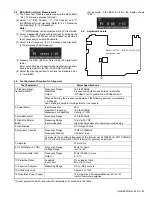
This transceiver has a test mode. To enter test mode, press and
hold the [
] key while turning the transceiver power ON. Before
the transceiver enters test mode, the frequency version informa-
tion appears on the LCD momentarily. Test mode can be inhibit-
ed by programming. To exit test mode, turn the transceiver
power OFF. The following functions are available in test mode.
• When the panel test mode is activated, the last used channel
and signaling numbers are displayed. When the panel test
mode is activated for the first time, the channel and signaling
numbers are 1.
• If test signaling 10 (P25 Phase1), 7 (P25 Phase2) and 7
(NXDN Mode) is selected, the result of Bit Error Rate (BER)
calculation is displayed on the LCD.
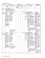
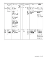
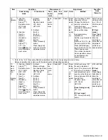
4.2.2 Key operation
*1: When the mode is selected as Analog, this function is en-
abled.
*2: When the mode is selected as P25, bandwidth is fixed to Nar-
row.
Power switch
Channel Up/Down key
Volume Up/Down key
MIC jack
Auxiliary (orange) key
KMC-36 (OPTION)
Keypad
[PTT]
Key
"Func" not appears on the sub LCD display
Function
Display
[+]
Push: Volume up
Hold: Volume up continu-
ously
-
[-]
Push: Volume down
Hold: Volume down con-
tinuously
-
[
]
Push: Test channel up
Hold: Test channel up
continuously
Channel No.
[
]
Push: Test channel down
Hold: Test channel down
continuously
Channel No.
[
]
Push: Squelch level up *1
Hold: Squelch off
Squelch level
Squelch off: icon
appears
[
]
Wide/Narrow/
Very Narrow *2
Wide : "w"
Narrow: "n"
Very Narrow: "v"
[ ]
Shift to panel tuning
mode
-
[
]
Function on
"Func" appears on the
sub LCD display
[ ]
MSK 1200bps and
2400bps *1
2400bps:
icon
appears
[ ]
Push: Test signaling up
Hold: Test signaling up
continuously
Signaling No.
[AUX
(Orange)]
-
-
[PTT]
Transmit
-
[0] to [9]
and
[#], [ ]
-
-
Key
"Func" appears on the sub LCD display
Function
Display
[+]
P25 Modulation Type
(C4FM/LSM) *3
LSM :
icon appears
[-]
Function off
-
[
]
Talk Around on/off
On:
icon appears
[
]
Mode selection
Analog/P25 Phase1
/P25 Phase2/NXDN
Analog: "A"
P25 Phase1: "P1"
P25 Phase2: "P2"
NXDN: "N"
[
]
-
-
Summary of Contents for NX-5700
Page 106: ...MEMO ...
Page 137: ...MEMO ...

