NXR-800H
24
D9
SW
D13
SW
Q25
SW
Q32
SW
Q31
SW
Q26
SW
L46,52
XF1
L74,90
XF3
Q19
Q28
Analog Wide
8WR
8WR
D10
SW
D14
SW
L47,53
XF2
L75,91
XF4
Q20
Q29
Analog Narrow
NXDN Narrow
NXDN Very-Narrow
8NR
8NR
+8V
IF_SW
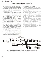
4-4. Demodulator circuits
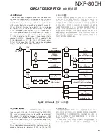
The desired signal that passed through the 1st-IF circuits
passes through the distributor consisting of LC parts and is
fed to the IF system IC_IC12, IC13. The signal in Analog_
Wide or Analog_Narrow mode is mixed with the second
local oscillator hetero signal by the mixer in IC12. 450kHz is
produced as the 2nd Intermediate Frequency (IF2).
It passes through D15, CF2, D16, D19, CF5 and D20 path
if the modulation mode is Analog_Wide. It passes through
D15, CF3, D16 and D19, CF7 and D20 path if the modulation
mode is Analog_Narrow. The base band signal FM-detected
by the quadrature detection circuit consisting of L128, Q57,
and Q58 and is amplifi ed to a signal level of approximately
100mVrms by IC20 and is then transmitted to the control
unit (X53-413) from CN42 (pin12).
The signal in NXDN_Narrow or NXDN_Very-Narrow mode
is mixed with the second local oscillator hetero signal by the
mixer in IC13. 450kHz is produced as the 2nd Intermediate
Frequency (IF2). Here, irrespective of modulation modes, it
passes through the CF4 and CF6 path. It is transmitted as
the base band signal via IC14 to the CN43 control unit, X53-
414.
CF2, CF3, CF4, CF5, CF6 and CF7 are hexode Ceramic
Filters. They are BPF for removing spurious noise occurring
close to the desired signal.
4-5. Squelch circuit
The desired noise of the noise component output from IF
system IC_IC12 (pin18) is extracted by the BPF. After pass-
ing through Q40, it is DC-detected as the squelch voltage by
D17, D18 and input to ADC_IC30 (pin11).
The MPU mounted in the control unit (X53-413) compares
it with a predetermined reference voltage and turns the Au-
dio signal on and off. The strength of the receiver signal in-
put from CN5 is output as the RSSI voltage from IF system
IC_IC12 (pin21), and is input to_IC30 (ADC) pin12 via IC29
A/2.
CIRCUIT DESCRIPTION /
电路说明
Fig. 18 1st-IF circuits /
图 18 第 1 IF 电路
4-4. 解调器电路
通过第 1 IF 电路的所需信号通过由 LC 部分组成的分配器,
被送入 IF 系统 IC_IC12、IC13。模拟宽或模拟窄模式的信号
由 I C12 中的混频器与第二本地振荡器外差信号混合。产生
450kHz,作为第 2 中频 (IF2)。
如果调制模式为模拟宽,则它通过 D15、C F2、D16、D19、
C F5 和 D20 的路径。如果调制模式为模拟窄,则它通过 D15、
C F3、D16 和 D19、C F7 和 D20 的 路 径。 由 L128、Q57 和 Q58
组成的积分检测电路 F M 检测的基带信号被 I C20 放大到约
100m V r m s 的信号电平,然后从 C N42( 针脚 12) 传送到控制单
元 (X53-413)。
NXDN 窄或 NXDN 超窄模式的信号由 IC13 中的混频器与第二
本地振荡器外差信号混合。产生 450kHz,
作为第 2 中频 (IF2)。
在此处,不论调制模式如何,它都通过 C F4 和 C F6 路径。它
被作为基带信号经 IC14 发送到 CN43 控制单元、X53-414。
C F2、C F3、C F4、C F5、C F6 和 C F7 是六极管陶瓷滤波器。
它们是用于消除所需信号附近发生的寄生噪声的 BPF。
4-5. 静噪电路
从 I F 系统 I C _ I C12( 针脚 18) 输出的噪音分量的所需噪音
由 BPF 提取。通过 Q40 后,D17、D18 对其进行 DC 检波作为静
噪电压,并输入到 ADC_IC30( 针脚 11)。
装于控制单元 ( X53-413) 上的 M P U 将其与预定的基准电压
相比较,并打开和关闭音频信号。CN5 输出的接收机信号的强
度作为 RSSI 电压从 IF 系统 IC_IC12( 针脚 21) 输出,经 IC29
A/2 输入到 _IC30(ADC) 针脚 12。
Summary of Contents for NXR-800H
Page 180: ...1 E CN300 RX_IF_VN 168 ...


