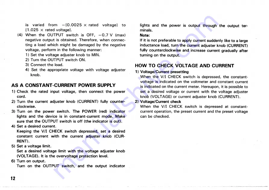
is varied from - [ 0 . 0 0 2 5
x
rated voltage] to
[1.025
x
rated voltage].
(4) When the OUTPUT switch is O F F , - 0 . 7 V (max)
negative output is obtained. Therefore, when connec-
ting a load which might be damaged by the negative
voltage, perform in the following manner:
1) Set the voltage adjuster knob to MIN.
2) Turn the OUTPUT switch ON.
3) Connect the load.
4) Set the appropriate voltage with voltage adjuster
knob.
A S A CONSTANT-CURRENT POWER SUPPLY
1) Check the rated input voltage, then connect the power
cord.
2) Turn the current adjuster knob (CURRENT) fully counter-
clockwise.
3) Turn on the power switch. The POWER (red) indicator
lights and the device is in constant-current mode. Make
sure that the OUTPUT switch is off (the indicator is out).
4) Set a desired current.
Keeping the V / I CHECK switch depressed, set a desired
constant current with the current adjuster knob (CUR-
RENT).
5) Set a voltage limit.
Set a desired voltage limit with the voltage adjuster knob
(VOLTAGE). It is the overvoltage protection level.
6) Turn on output.
Turn on the OUTPUT switch, and the output indicator
lights and the power is output through the output ter-
minals.
Note:
If it is not preferable to apply current suddenly like to a large
inductance load, turn the current adjuster knob (CURRENT)
fully counterclockwise and increase current gradually after
turning on the output.
HOW TO CHECK VOLTAGE AND CURRENT
1) Voltage/Current presetting
When the V / I CHECK switch is depressed, the constant-
voltage is indicated on the voltmeter and constant current
is indicated on the current meter. Hereupon, it is possible to
set a desired voltage or current with the voltage adjuster
knob (VOLTAGE) or current adjuster knob (CURRENT).
2) Voltage/Current check
When the V / I CHECK switch is depressed at constant-
current operation, the preset current and the preset voltage
can be checked.
12
Summary of Contents for PD110-3
Page 8: ...CONTROLS AND INDICATORS FRONT PANEL Fig 3 ...
Page 10: ...10 Fig 4 REAR PANEL ...
Page 26: ...DIMENSIONS Fig 2 0 26 ...


