Note:
The output voltage is determined with R
2
and Wet as given
above. The output voltage is 0 V if R
2
is infinite (open). Set
Vref
with the voltage control provided on the panel. To fix it or
set it externally, connect a 10 k ohm resistor which has a
good temperature characteristic across ® and ® according
to "Control by resistance (I)". The voltage control of the
panel is now ineffective.
Note:
Be sure to adjust the output voltage at OUTPUT ON mode. In
OUTPUT O F F or V/l CHECK mode, there is a slight error in
meter reading.
Control by external voltage
It is possible to output voltage which is proportional to
voltage.
1) Turn off power.
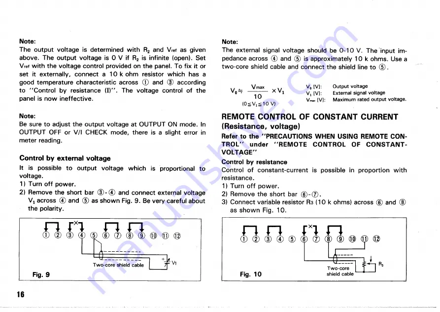
2) Remove the short bar ® - ® and connect external voltage
V
x
across (4) and © as shown Fig. 9. Be very careful about
the polarity.
Fig. 9
Note:
The external signal voltage should be 0-10
V .
The input im-
pedance across © and © is approximately 10 k ohms. Use a
two-core shield cabie and connect the shield line to © .
^ Vmax V
0
[ V ] : O u t p u t v o l t a g e
V
0 — ~~T
x
V
l V , [ V ] : E x t e r n a l s i g n a l v o l t a g e
V ™ , [ V ] : M a x i m u m r a t e d o u t p u t v o l t a g e .
( 0
S
V
! < 1 0 V )
REMOTE CONTROL OF CONSTANT CURRENT
(Resistance, voltage)
Refer to the " P R E C A U T I O N S WHEN USING REMOTE CON-
T R O L " under " R E M O T E C O N T R O L O F C O N S T A N T -
V O L T A G E "
Control by resistance
Control of constant-current is possible in proportion with
resistance.
1) Turn off power.
2) Remove the short bar © - ( 7 ) .
3) Connect variable resistor R 3 (10 k ohms) across © and ©
as shown Fig. 10.
16
T w o - c o r e s h i e l d c a b l e
Fig. 10
T w o - c o r e
s h i e l d c a b l e
R
3
Summary of Contents for PD110-3
Page 8: ...CONTROLS AND INDICATORS FRONT PANEL Fig 3 ...
Page 10: ...10 Fig 4 REAR PANEL ...
Page 26: ...DIMENSIONS Fig 2 0 26 ...


