S l a v e
S l a v e
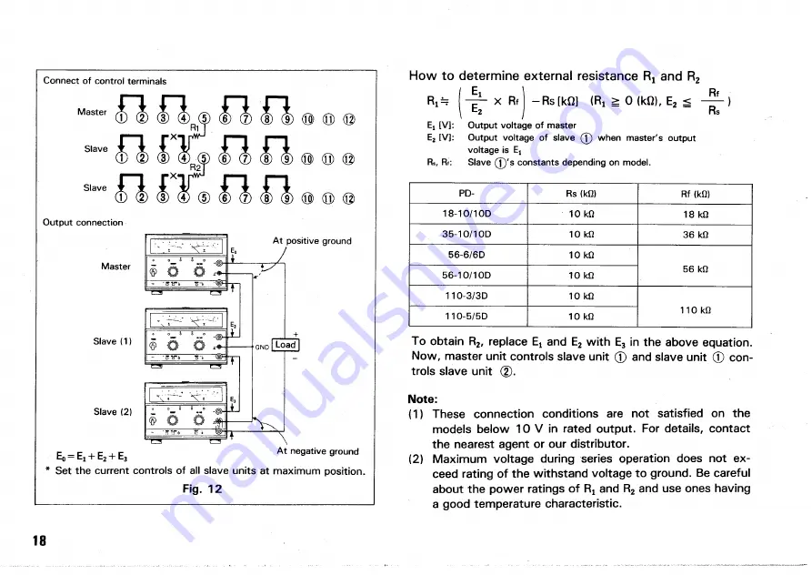
O u t p u t c o n n e c t i o n
M a s t e r
S l a v e ( 1 )
S l a v e ( 2 )
E
0
= E
1
+ E
2
+ E
3
A t n e g a t i v e g r o u n d
Set the current controls of all slave units at maximum position.
P D -
R s
(kQ)
R f
(kQ)
1 8 - 1 0 / 1 O D
1 0
kQ
1 8
kQ
3 5 - 1 0 / 1 O D
1 0
kQ
3 6
kQ
5 6 - 6 / 6 D
1 0
kQ
5 6
kQ
5 6 - 1 0 / 1 O D
1 0
kQ
5 6
kQ
1 1 0 - 3 / 3 D
1 0
kQ
1 1 0
kQ
1 1 0 - 5 / 5 D
1 0
kQ
1 1 0
kQ
To obtain R
2
, replace Ej and E
2
with E
3
in the above equation.
Now, master unit controls slave unit 0 and slave unit © con-
trols slave unit (2).
Note:
(1) These connection conditions are not satisfied on the
models below 10 V in rated output. For details, contact
the nearest agent or our distributor.
(2) Maximum voltage during series operation does not ex-
ceed rating of the withstand voltage to ground. Be careful
about the power ratings of R
a
and R
2
and use ones having
a good temperature characteristic.
18
C o n n e c t o f c o n t r o l t e r m i n a l s
M a s t e r
A t p o s i t i v e g r o u n d
L o a d
Fig. 12
How to determine external resistance
R
t
and R
2
R
t
=
I
4
1
"
x Rf ] - R s [kO] (Ri ^ 0 (kfi), E
2
< )
\
b
2
/ Rs
E j [ V ] : O u t p u t v o l t a g e o f m a s t e r
E
2
[ V ] : O u t p u t v o l t a g e o f s l a v e 0 w h e n m a s t e r ' s o u t p u t
v o l t a g e i s E ,
R
s
, Rt:
S l a v e
( J
) ' s c o n s t a n t s d e p e n d i n g o n m o d e l .
Summary of Contents for PD110-3
Page 8: ...CONTROLS AND INDICATORS FRONT PANEL Fig 3 ...
Page 10: ...10 Fig 4 REAR PANEL ...
Page 26: ...DIMENSIONS Fig 2 0 26 ...


