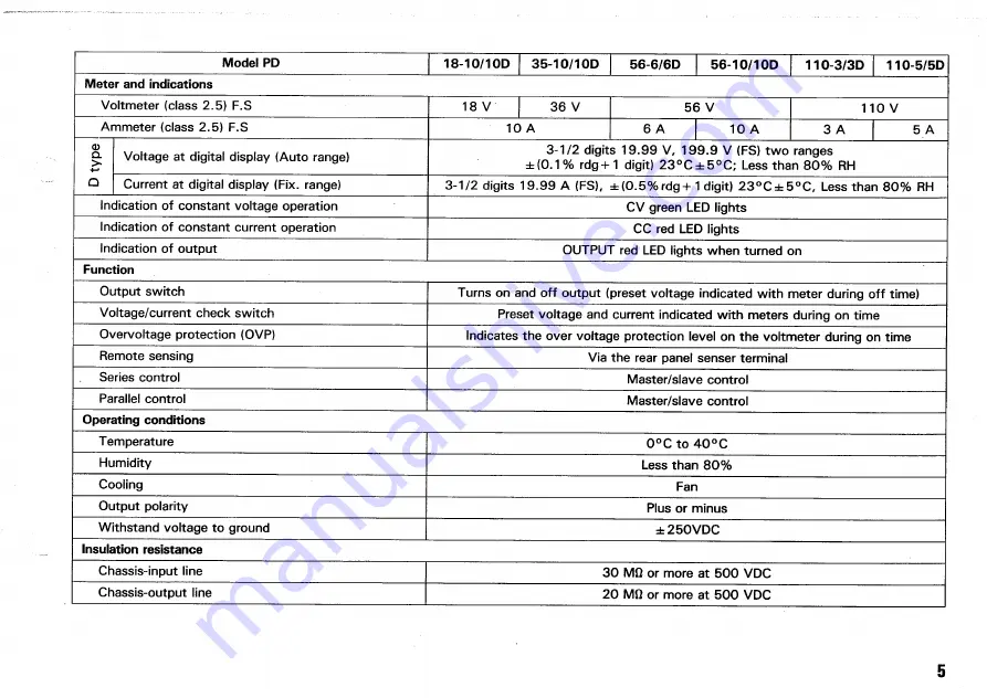
Model PD
18-10710D
3 5 - 1 0 / 1 0 D
5 6 - 6 / 6 D
56-10/1OD
1 1 0 - 3 / 3 D
110-5/5D
Meter and indications
Voltmeter (class 2 . 5 ) F . S
18 V
3 6 V
5 6 V
1 1 0 V
Ammeter (class 2 . 5 ) F . S
1 0 A
6 A
1 0 A
3 A
5 A
D
typ
e
Voltage at digital display (Auto range)
3 - 1 / 2 digits 1 9 . 9 9 V , 1 9 9 . 9 V ( F S ) t w o ranges
± ( 0 . 1 % r d g + 1 digit) 2 3 ° C ± 5 ° C ; L e s s than 8 0 % R H
D
typ
e
Current at digital display ( F i x . range)
3 - 1 / 2 digits 1 9 . 9 9 A ( F S ) , ± ( 0 . 5 % r d g + 1 digit) 2 3 ° C ± 5 ° C , Less than 8 0 % R H
Indication of constant voltage operation
C V green L E D lights
Indication of constant current operation
C C red L E D lights
Indication of output
O U T P U T red L E D lights w h e n turned on
Function
Output s w i t c h
Turns on and off output (preset voltage indicated with meter during off time)
Voltage/current check s w i t c h
Preset voltage and current indicated w i t h meters during on time
Overvoltage protection ( O V P )
Indicates the over voltage protection level on the voltmeter during on time
Remote sensing
Via the rear panel senser terminal
Series control
Master/slave control
Parallel control
Master/slave control
Operating conditions
Temperature
0 ° C t o 4 0 ° C
Humidity
L e s s than 8 0 %
Cooling
Fan
Output polarity
Plus or minus
Withstand voltage to ground
± 2 5 0 V D C
Insulation resistance
Chassis-input line
3 0 MQ or more at 5 0 0 V D C
Chassis-output line
2 0 MQ or more at 5 0 0 V D C
5
Summary of Contents for PD110-3
Page 8: ...CONTROLS AND INDICATORS FRONT PANEL Fig 3 ...
Page 10: ...10 Fig 4 REAR PANEL ...
Page 26: ...DIMENSIONS Fig 2 0 26 ...


