PW-A
19
CIRCUIT DESCRIPTION
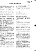
7. External control (CN..) These are directly connected
with the CPU ports. D1 to D6 are used for protection.
Pin 7 has Q1 and
Q2 for both input and output. PH30 is
used for isolation.
CN5-1 -- The MAIN OUTPUT is turned on when this
terminal goes Low.
CN5-2 -- The voltage and current set values change
into the PRESET4 values when this terminal goes Low.
CN5-3 -- The voltage and current set values change
into the PRESET3 values when this terminal goes Low.
CN5-4 -- The voltage and current set values change
into the PRESET2 values when this terminal goes Low.
CN5-5 -- The voltage and current set values change
into the PRESET1 values when this terminal goes Low.
CN5-7 -- The MAIN OUTPUT is turned off when this
terminal goes Low. It goes Low when the OHA
condition is established.
AC power supply circuit
8. J1: AC inlet
A1 -- A switch for changing the input AC voltage
CN11 -- Fuse holder
C38 to 41 -- Noise-reducing
capacitors
Summary of Contents for PW-A series
Page 57: ...A C E G I B D F H J SCHEMATIC DIAGRAM PW A ...
Page 58: ...SCHEMATIC DIAGRAM L N P R T M O Q S PW A ...
Page 59: ...SCHEMATIC DIAGRAM U W Y AA AC V X Z AB AD PW A ...
Page 60: ...AF AH AJ AL AN AG AI AK AM SCHEMATIC DIAGRAM PW A ...
Page 61: ...AO AQ AS AU AW AP AR AT AV AX SCHEMATIC DIAGRAM PW A ...
Page 62: ...PW A Y39 4160 00 AY BA BC AZ BB ...
Page 63: ...BE BG BI BK BM BF BH BJ BL SCHEMATIC DIAGRAM PW A ...
Page 64: ...BN BP BR BT BV BO BQ BS BU BW SCHEMATIC DIAGRAM PW A ...


