PW-A
33
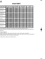
ADJUSTMENT
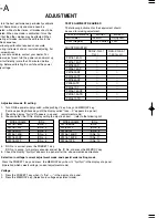
MODEL NAME
SETTING VOLTAGE
ADJUSTMENT
VOLTAGE
ADJUSTMENT
RANGE
SHUNT
REGISTER
CH1
0.300 A
0.300 V
PW18-3ADP
CH2
0.300 A
0.300 V
CH1
0.100 A
1.000 V
CH2
0.200 A
0.100 V
PW18-2ATP
CH3
0.200 A
0.200 V
CH1
0.300 A
0.300 V
PW16-5ADP
CH2
0.500 A
0.500 V
CH1
0.300 A
0.300 V
CH2
0.300 A
0.300 V
PW8-3ATP
CH3
0.150 A
0.150 V
CH1
0.100 A
1.000 V
CH2
0.100 A
1.000 V
PW26-1AT
CH3
0.500 A
0.500 V
CH1
0.150 A
0.150 V
PW36-1.5ADP
CH2
0.150 A
0.150 V
CH1
0.130 A
0.130 V
CH2
-0.130 A
-0.130 V
PW18-1.3ATS
CH3
0.500 A
0.500 V
CH1
0.100 A
1.000 V
CH2
0.100A
1.000 V
PW26-1ATS
CH3
0.500 A
0.500 V
After current
adjustment end, when adjust other channels, adjust in the same procedure from 5-4-2.
When ending current adjustment, press the long pushing of KEYLOCK key (more than 2 seconds), cancel the current
adjustment mode.
4. The end of adjustment
If complete all adjustments of the voltage current of each
output, turn OFF a power supply switch.
(Or press the long pushing of KEYLOCK key {2 seconds or more} several times {3 times or more}, and escape from
the adjustment mode.
And turn OFF the power supply switch)
*
The model with YB is all the same as the basic model.
±
1 mV
1
Ω
±
1 mV
1
Ω
±
1 mV
1
Ω
±
1 mV
1
Ω
±
1 mV
1
Ω
±
1 mV
1
Ω
±
1 mV
1
Ω
±
1 mV
1
Ω
±
1 mV
1
Ω
±
1 mV
1
Ω
±
1 mV
1
Ω
±
1 mV
1
Ω
±
1 mV
1
Ω
±
1 mV
1
Ω
±
1 mV
1
Ω
±
1 mV
1
Ω
±
1 mV
1
Ω
±
1 mV
1
Ω
±
1 mV
1
Ω
±
1 mV
1
Ω
±
1 mV
1
Ω
Summary of Contents for PW-A series
Page 57: ...A C E G I B D F H J SCHEMATIC DIAGRAM PW A ...
Page 58: ...SCHEMATIC DIAGRAM L N P R T M O Q S PW A ...
Page 59: ...SCHEMATIC DIAGRAM U W Y AA AC V X Z AB AD PW A ...
Page 60: ...AF AH AJ AL AN AG AI AK AM SCHEMATIC DIAGRAM PW A ...
Page 61: ...AO AQ AS AU AW AP AR AT AV AX SCHEMATIC DIAGRAM PW A ...
Page 62: ...PW A Y39 4160 00 AY BA BC AZ BB ...
Page 63: ...BE BG BI BK BM BF BH BJ BL SCHEMATIC DIAGRAM PW A ...
Page 64: ...BN BP BR BT BV BO BQ BS BU BW SCHEMATIC DIAGRAM PW A ...

