background image

TK-2317

19

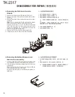
8. Mounting the Chassis to the Case 

    Assembly

1.  Confirm that the waterproof packing attached to the 

circumference of the chassis is securely inserted in the 
groove of the chassis 

a

.

2.  Insert the upper part of the chassis into the case assem-

bly 

b

.

3.  Press the chassis 

c

 and the case assembly together to 

attach them.


Caution: If the packing of the SP/MIC does not come 
to the correct position after attaching the chassis to the 
case assembly, reposition the packing with your fi ngers.

9.  Attaching the Antenna Receptacle to 

the Chassis


Screw the antenna receptacle to the chassis in the or-
der shown in the drawing so that the antenna receptacle 
comes to the center of the case hole.

DISASSEMBLY FOR REPAIR /

维修拆卸

a

b

Tighten this screw second

Tighten this screw first.

8. 安装机壳机架

1. 确认机架四周的防水垫是否确实进入机壳的槽里。

a

2. 把机架上部插到机壳里。

b

3. 按压机架

c

,使机架和机壳成为一个整体。

  注∶把机架安装到机壳上后,如果 SP/MIC  不在正确的位

置的话,请用手指调整到正确的位置。

9. 把天线座安装到机架

  为了能把天线座安装到机芯孔的中心,在将天线座安装到

机架时,请按照图示的顺序固定螺丝。

然后再拧紧此螺丝。

首先拧紧此螺丝。

Summary of Contents for TK-2317

Page 1: ...or Knob Volume Plastic cabinet assy Button knob PTT Key top 7key KRA 26 Option Helical antenna K29 9427 03 Knob Selector K29 9309 13 Knob Volume Button knob PTT K29 9425 03 K29 9426 03 SIDE1 SIDE2 Button knob Key top 7key K29 9463 12 Plastic cabinet assy A02 4095 23 无铅焊接通信产品 保护环境建伍领先 注意 本产品是无铅化焊接产品 在维修时请使用无铅焊锡 和相应的焊接工具 详细事项请访问如下网址了解 http www kenwoodhk com hk C version C 版本 天线 按钮 PTT 钮扣按钮 顶端按键 7 键 ...

Page 2: ...AGRAM 56 BLOCK DIAGRAM 62 LEVEL DIAGRAM 64 OPTIONAL ACCESSORIES KNB 29N Ni MH Battery Pack 65 KNB 45L Li ion Battery Pack 65 KNB 53N Ni MH Battery Pack 65 KMC 48GPS GPS Speaker Microphone 65 SPECIFICATIONS BACK COVER CONTENTS 目录 概 述 3 系统体系 4 模式组合 5 维修拆卸 15 电路说明 21 半导体数据 29 元件说明 31 零 件 表 33 部件分解图 40 包 装 41 调 整 42 印刷电路板 收发单元 X57 7880 20 52 原 理 图 56 方 块 图 62 电 平 图 64 可选附件 KNB 29N 镍氢电池 65 KNB 45L 锂离子电...

Page 3: ...ll required service information for the equipment and is current as of the pub lication date Changes which may occur after publication are covered by either Service Bulletins or Manual Revisions These are issued as required ORDERING REPLACEMENT PARTS When ordering replacement parts or equipment informa tion the full part identification number should be included This applies to all parts components...

Page 4: ... Are you using the speaker microphone A personal computer programming interface KPG 22 22A and FPU programming software are required for programming The frequency TX power HI LOW and signaling data are programmed for the transceiver YES NO KMC 21 KMC 45 or KMC 48GPS Speaker microphone Option Are you using the optional antenna YES NO KRA 22 or KRA 26 Optional antenna TX RX 136 174 5 0W TK 2317C Fre...

Page 5: ...lone mode B Power ON Two seconds Firmware version information mode Side1 Side2 Power ON Two seconds Self programming mode S Power ON Two seconds 3 PC Mode 3 1 Preface The transceiver is programmed by using a personal com puter a programming interface KPG 22 22A USB adapter KCT 53U and FPU programming software The programming software can be used with a PC Fig ure 1 shows the setup of a PC for prog...

Page 6: ... KPG 22A to a USB port on a computer When using the KCT 53U install the supplied CD ROM with driver software in the computer The KCT 53U driver runs under Windows 2000 XP or Vista 32 bit 3 5 FPU Programming Software Description The FPU is the programming software for the transceiver supplied on a CD ROM This software runs under windows XP Vista or 7 on a PC The software on this disk allows a user ...

Page 7: ...ENT 模式组合 D SUB Transceiver Transceiver Transceiver KPG 22 PC D SUB KPG 22A PC USB KPG 22A KCT 53U PC PC KPG 22 or KPG 22A or KPG 22A KCT 53U Illustration is KPG 22 FPU T uning cable E30 3216 05 Gray Gray Black 1 5D XV Lead wire 1 5D XV Shield wire SP MIC 9 pin 25 pin Fig 1 图 1 KPG 22 或 KPG 22A 或 KPG 22A KCT 53U 插图为 KPG 22 灰色 灰色 黑色 1 5D XV 导线 1 5D XV 屏蔽线 调谐电缆 25 针 9 针 手持对讲机 手持对讲机 手持对讲机 3 6 使用 PC 编程...

Page 8: ...rget unit s Scan and Key lock functions will return to their default values Scan OFF Key lock OFF 11 The source will remain in clone mode after cloning The target unit will return to user mode after a successful cloning Note The dealer can clone data to two or more transceivers by repeating the above procedures If the transceivers wireless clone Mode is configured as Disabled the transceiver canno...

Page 9: ...u press the C key the currently selected num ber is determined If you press the A key the least digit of the password is deleted If you press the S key after entering the password in this procedure FRQTBL 1 is displayed if the entered pass word is correct If the password is incorrect CLN LOCK R CLN LOCK W is redisplayed with error tone Clone frequency table No Operating frequency 136 174 MHz 1 136...

Page 10: ...ey the least digit of the password is deleted If you press the S key after entering the password in this procedure SELF is displayed if the entered password is correct If the password is incorrect SLF LOCK R SLF LOCK W is redisplayed 6 3 Channel Selection Mode In this mode the Zone or Channel can be selected Press and hold the S key for 2 seconds while turning the transceiver power on to enter sel...

Page 11: ...ng items can be selected RX frequency RX signaling TX frequency TX signaling RF power Hi Low Scan Del Add Beat shift on off Compander on off Band W N When the S key is pressed in the Channel Selection mode the transceiver enters the Item Selection mode Key operation Key Key Function Selector The selected item changes Side1 No action Side2 No action S Enter the Item Setting mode A Return to the Cha...

Page 12: ...ing only Side1 No action Side2 No action S tore the current settings and return to the Item Selection mode A MHz digit of the frequency blinks RX TX fre quency only The icon of the current signaling configuration blinks RX TX signaling only A Abort the current settings and return to the Item Selection mode without backup B Toggle Decrease the blinking value C Toggle Increase the blinking value REA...

Page 13: ...low chart Data password S Power ON SLF LOCK R or Display SLF LOCK W SELF Zone Channel Self programming mode S S A Channel selection mode S A Zone selection Channel selection Item setting mode S Read authorization password Overwrite password entry 6 digits When the Read authorization password is set to the transceiver When the Overwrite authorization password is set to the transceiver Selector B Zo...

Page 14: ...or 1 RX frequency or 3 TX frequency S A MHz setting Current setting value Value is not set 136 00000 Display 136 00000 136 00000 STP 5 00K Selector A kHz setting Selector A Channel step Selector B C B C B C S S S S Cleared A Frequency clear Selector 2 RX signaling or 4 TX signaling S A OFF 2 RX signaling or 4 TX signaling OFF DQT I Display TONE OFF QT 67 0 DQT 023N DQT 023 I Selector A QT Selector...

Page 15: ...t to cut the speaker and microphone lead 2 Detach the solder of speaker and microphone lead from the PCB beforehand 3 Remove the packing e from the SP MIC jack of the TX RX unit DISASSEMBLY FOR REPAIR 维修拆卸 b a c c d 1 从机体上拆卸机壳 1 拆卸选择器旋钮 a 和音量旋钮 b 2 拧下 2 个螺丝 c 3 从机体拉出并卸下机壳 d 使用一字螺丝刀容易拉出机壳 2 从机架卸下支架 1 从机架卸下支架 注意 小心不要折断扬声器引线和麦克风引线 2 卸下 PC 板上的扬声器引线和麦克风引线上的焊锡 3 卸下 SP MIC 连接器的橡胶垫 BLU YEL RED BLK S S M M...

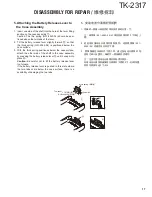
Page 16: ...nd remove the TX RX unit from the chassis j 4 Removing the Battery Release Lever from the Case Assembly 1 Press the upper part of the lever toward the inside of the case assembly One side of the shaft will be removed a 2 Lift and remove the battery release lever from the case assembly b Note Scratch and widen the glue hole if there is difficulty in removing the other end of the shaft No glue is re...

Page 17: ...r side of the shaft to the case assembly by pressing the battery release lever c until it snaps into place d Caution Be careful not to tilt the battery release lever too forward If the battery release lever is pushed in this state where the two tabs come below the case surface there is a possibility of damaging the two tabs DISASSEMBLY FOR REPAIR 维修拆卸 A thin spring Shaft Tow tabs A thick spring a ...

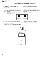
Page 18: ...ve terminal to the chassis using the following procedures before mounting the TX RX unit onto the chassis 1 Remove the holder assembly b from the packing a of the positive terminal 2 Mount the packing of the positive terminal into the chas sis hole c 3 Mount the holder assembly into the packing of the posi tive terminal d DISASSEMBLY FOR REPAIR 维修拆卸 a b c d e f a c d b 6 电池分离拨杆的组装方法 1 请把拨杆 b 置于止动器...

Page 19: ...he correct position after attaching the chassis to the case assembly reposition the packing with your fingers 9 Attaching the Antenna Receptacle to the Chassis Screw the antenna receptacle to the chassis in the or der shown in the drawing so that the antenna receptacle comes to the center of the case hole DISASSEMBLY FOR REPAIR 维修拆卸 a b Tighten this screw second Tighten this screw first 8 安装机壳机架 1...

Page 20: ...g the nuts of the vol ume knob and selector knob Jig Part No W05 1012 00 11 Screw sequence for mounting the TX RX unit to the chassis Attach the TX RX unit to the chassis using the screws in the order shown in the drawing below for Volume knob Long for Selector knob Short TX RX UNIT Component side view g h i d e b f c a k j 10 关于音量旋钮和选择器旋钮的螺母 音量旋钮和选择器旋钮的螺母形状不同 颜色高度也不同 因此请注意 音量旋钮螺母为银色 选择器旋钮的螺母 为金色 ...

Page 21: ...5 AF PA BPF1 1st Local BPF CF402 CF401 2 1 Front End RF Amplifier Circuit The signal coming from the antenna passes through the transmit receive switching diode circuit D201 D202 D203 and D204 and a BPF L418 and L419 and is then ampli fied by the RF amplifier Q407 The resulting signal passes through a BPF L419 L418 L416 and L414 and goes to the mixer These BPFs are ad justed by variable capacitanc...

Page 22: ...tor with the ceramic discriminator CD401 The demodu lated signal is routed to the audio circuit 2 4 Wide Narrow Switching Circuit Wide and narrow settings can be made for each channel by switching the ceramic filters CF401 narrow The second IF signal always passes the ceramic filters CF402 Wide The wide and narrow switching data is output from the MCU IC820 D401 and D402 are switched to ceramic fi...

Page 23: ...tput signal passes through the amplifier IC3 and goes to the TCXO modulation input CIRCUIT DESCRIPTION 电路说明 3 2 Driver and Final Amplifier Circuit The signal from the T R switch D18 is on is amplified by the RF AMP Q201 and pre drive amplifier Q203 to 50mW The output of the pre drive amplifier is amplified by the drive amplifier Q204 and the RF final amplifier Q205 to 5 0W 1W when the power is low...

Page 24: ...ol voltage obtained from the phase comparator IC1 to the variable ca pacitance diodes D4 D6 D8 and D9 in transmitting mode and D10 and D12 in receiving mode The TX RX pin of IC820 goes high in transmitting mode causing Q7 and Q4 to turn off and Q5 turn on The TX RX pin goes low in receiving mode The output from Q4 and Q5 are amplified by a buffer am plifier Q8 and Q2 and then sent to the PLL IC Th...

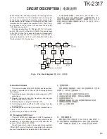
Page 25: ...ta to the PLL 4 Controlling squelch on off via the DC voltage from the squelch circuit 5 Controlling the audio mute circuit via the decode data in put 6 Transmitting tone and encode data 5 1 Frequency Shift Circuit The MCU IC820 and baseband IC IC812 operates at a clock frequency of 19 2MHz The oscillator circuit has the baseband IC This oscillator has a circuit that shifts the fre quency via Beat...

Page 26: ...eeps while the PTT switch is pressed Low battery warning Battery status The red LED blinks during transmission The battery voltage is low but the transceiver is still usable The red LED blinks and the warning tone beeps while the PTT switch is pressed The battery voltage is lowand the transceiver cannotbe used to make calls IC812 Baseband IC H OFF L ON MCU XIN X802 39 40 XOUT XIN Q806 C846 R857 MC...

Page 27: ...and goes to the VCO and TCXO X1 modulation input after passing through the D A converter inside the baseband IC IC812 for BAL adjustment CIRCUIT DESCRIPTION 电路说明 C B A S KEY1O KEY2O KEY3O KEY4O KEY1I KEY2I KEY3I KEY4I EN2 EN1 Selector IC820 MCU PF2 PF1 PTT Side1 Side2 PTT HSDENC LSDO IC820 MCU IC812 Baseband IC TCXO 3 2 21 MIC 23 MOD1 VCO 24 MOD2 18 ALT Fig 10 Key input 图 10 键输入 Fig 11 Encode 图 11...

Page 28: ... goes to IC812 The decoded information is then processed by the MCU 7 Power Supply There are five 5V power supplies and three 3 3V power supplies 50M 50V 50C 50R 50T 33M 33MS and 33B 50M and 33M are always output while the power is on 33MS is always output but turns off when the power is turned off to prevent malfunction of the MCU 50C is a common 5V and is output when SAVE is not set to ON 50R is...

Page 29: ... 32 EP_CLK O EEPROM IC clock output 33 CM_DTO O Baseband IC data output 34 EPM O For FDT tool 35 5RC O 5R control output 36 EP_WP O EEPROM IC write protect output 37 EP_DTI I EEPROM IC data input 38 EP_CS O EEPROM IC chip select output 39 CE O For FDT tool 40 CM_CLK O Baseband IC clock output SEMICONDUCTOR DATA 半导体数据 微处理器 F363BEDFEKDLB 收发单元 IC820 管脚号 端口名称 输入 输出 功 能 1 BSHIFT 输出 拍频偏移 2 LSDO 输出 低速数据输...

Page 30: ...H WID L NAR 69 ASSIST O Assist switch 70 AF_MUT O Speaker mute output 71 MIC_MT O Mic mute output 72 MAN_DN I MAN down 73 5CC O 5C control output 74 LEDBLU O Blue LED light control 75 AVSS GND 76 LEDGRN O Green LED light control 77 VREF 3 3V for A D reference 78 AVCC 3 3V 79 LEDRED O Red LED light control 80 OPTDET I Option detection input SEMICONDUCTOR DATA 半导体数据 管脚号 端口名称 输入 输出 功 能 41 CM_DTI 输入 基...

Page 31: ...fier Q301 Transistor APC switch Q303 FET APC switch control Q304 Transistor APC switch Q305 FET APC switch Q306 Transistor APC switch Q401 Transistor W N switch control Q403 Transistor Tripler Q404 Transistor W N switch Q405 Transistor IF amplifier Q406 FET Mixer Q407 FET RF amplifier RX Q801 FET LED switch RED GRN COMPONENTS DESCRIPTION 元件说明 收发单元 X57 7880 20 有关号码 零件名称 说 明 IC1 IC PLL 系统 IC2 IC 直流放...

Page 32: ...ilter switch D404 405 Variable capaci tance diode RX BPT tune D407 408 Variable capaci tance diode RX BPT tune D801 LED Busy LED green D803 Diode Protection D804 LED Signal LED blue D805 LED TX LED red D806 Zenor diode Over voltage prevention D807 808 Diode Mic level Detection D809 810 Diode VOX level Detection D817 Diode Speed up back light D818 821 LED LCD back light D824 LED LCD back light D829...

Page 33: ... 03 HOLDER SP MIC ACCESSORY 50 1C J29 0734 05 BELT CLIP ACCESSORY 52 2A J82 0127 05 FPC 54 1B K29 9309 13 KNOB VOL 55 1A K29 9425 03 BUTTON KNOB PTT 56 1A K29 9426 03 BUTTON KNOB SIDE1 2 57 1B K29 9427 03 KNOB SELECTOR 58 1A K29 9463 12 KEY TOP 7KEY A 2A N14 0848 05 CIRCULAR NUT SELECTOR B 2B N14 0849 05 CIRCULAR NUT VOL C 2A N30 2604 48 PAN HEAD MACHINE SCREW SMA D 3A N30 2606 48 PAN HEAD MACHINE...

Page 34: ... CC73GCH1H470J CHIP C 47PF J C238 CC73GCH1H120J CHIP C 12PF J C239 CC73GCH1H220J CHIP C 22PF J C240 CK73GB1H102K CHIP C 1000PF K C241 CC73GCH1H1R5B CHIP C 1 5PF B C243 CK73GB1H102K CHIP C 1000PF K C244 CK73HB1H471K CHIP C 470PF K C245 CC73HCH1H180J CHIP C 18PF J C246 CC73GCH1H110J CHIP C 11PF J C247 CK73GB1H102K CHIP C 1000PF K C248 CC73GCH1H100C CHIP C 10PF C C249 CC73GCH1H150J CHIP C 15PF J C250...

Page 35: ...IP C 0 10UF K C850 CK73HB1H102K CHIP C 1000PF K C852 CK73HB1A104K CHIP C 0 10UF K C857 CK73HB1H332K CHIP C 3300PF K C858 CK73HB1E682K CHIP C 6800PF K C859 CK73HB1A105K CHIP C 1 0UF K C861 CK73HB1H102K CHIP C 1000PF K C863 CK73HB1E103K CHIP C 0 010UF K C865 CK73HB1H471K CHIP C 470PF K C866 CK73GB0J106K CHIP C 10UF K C869 CK73GB0J106K CHIP C 10UF K C872 CK73HB1H102K CHIP C 1000PF K C873 CK73HB1E103K...

Page 36: ...TE L416 L41 6878 14 SMALL FIXED INDUCTOR 68NH L418 L41 6878 14 SMALL FIXED INDUCTOR 68NH L419 L41 5678 14 SMALL FIXED INDUCTOR 56NH L420 L40 4775 57 SMALL FIXED INDUCTOR 47NH L801 L92 0472 05 CHIP FERRITE L802 803 L92 0161 05 BEADS CORE X1 L77 3050 05 TCXO 16 8MHZ X802 L78 1434 05 RESONATOR 19 2MHZ XF401 L71 0671 05 MCF 49 95MHZ CP1 RK74HB1J101J CHIP COM 100 J 1 16W CP802 RK75HA1J102J CHIP COM 1 0...

Page 37: ... R411 RK73HB1J103J CHIP R 10K J 1 16W R414 RK73HB1J101J CHIP R 100 J 1 16W R415 RK73HB1J182J CHIP R 1 8K J 1 16W R416 RK73HB1J122J CHIP R 1 2K J 1 16W R417 RK73HB1J154J CHIP R 150K J 1 16W R419 RK73HB1J823J CHIP R 82K J 1 16W R421 422 RK73HB1J332J CHIP R 3 3K J 1 16W R423 RK73HB1J222J CHIP R 2 2K J 1 16W R424 RK73HB1J182J CHIP R 1 8K J 1 16W R425 RK73HB1J000J CHIP R 0 J 1 16W R426 RK73HB1J100J CHI...

Page 38: ...15 RK73HB1J152J CHIP R 1 5K J 1 16W R916 RK73HB1J123J CHIP R 12K J 1 16W R918 RK73HB1J473J CHIP R 47K J 1 16W R919 RK73HB1J682J CHIP R 6 8K J 1 16W R920 RK73HB1J561J CHIP R 560 J 1 16W R921 922 RK73HB1J473J CHIP R 47K J 1 16W R923 RK73HB1J151J CHIP R 150 J 1 16W R924 RK73HB1J474J CHIP R 470K J 1 16W R925 RK73HB1J334J CHIP R 330K J 1 16W R926 RK73HB1J274J CHIP R 270K J 1 16W R927 RK73HB1J473J CHIP ...

Page 39: ...SISTOR Q11 SSM3J05FU F FET Q12 2SK1830F FET Q201 2SC5636 TRANSISTOR Q203 2SC5455 A TRANSISTOR Q204 RD01MUS1 T113 FET Q205 RD07MUS2BT112 FET Q301 RT1N140U T111 TRANSISTOR Q303 2SK1830F FET Q304 RT1N141U T111 TRANSISTOR Q305 2SK1824 A FET Q306 RT1P441U T111 TRANSISTOR Q401 RT1N441U T111 TRANSISTOR Q403 KTC4080E P TRANSISTOR Q404 RT1P441U T111 TRANSISTOR Q405 KTC4080E P TRANSISTOR Q406 3SK318 FET Q40...

Page 40: ...22 13 52 36 24 W1 21 56 TX RX unit 49 64 41 25 702 27 19 14 16 39 VR1 C A B C Dx2 E E E E E E Ex2 Ex2 55 701 X57 28 101 46 15 5 Ex2 34 X57 107 X57 103 X57 102 X57 105 X57 109 EXPLODED VIEW 部件分解图 Parts with the exploded numbers larger than 700 are not supplied 编号大于 700 的零件未提供分解图 ...

Page 41: ...ion manual B62 2261 00 704 Protection bag 50 Belt clip KBH 10 3 Cap 60 Screw set 48 Holder SP MIC 706 Packing fixture 707 Item carton case PACKING 包装 Parts with the exploded numbers larger than 700 are not supplied 编号大于 700 的零件未提供分解图 ...

Page 42: ...Supply 5V to 10V approx 3A Useful if ammeter equipped Antenna connector adapter The antenna connector of this transceiver uses an SMA terminal Use an antenna connector adapter SMA f BNC f or SMA f N f for adjustment The adapter is not provided as an option so buy a commercially available one Repair Jig Chassis Use jig part No A10 4215 03 for repairing the trans ceiver Place the TX RX unit on the j...

Page 43: ...频谱分析仪 测量范围 直流到 1GHz 或更高 12 轨迹发生器 中心频率 50kHz 到 600MHz 输出电压 100mV 或更高 13 8Ω 假负载 大约 8Ω 3W 14 可调电源 5V 到 10V 大约 3A 配备了电流表时更好 天线接口转换头 此手持对讲机的天线接口使用 SMA 终端 使用天线接口转换头 SMA f BNC f 或 SMA f N f 进 行调整 转换头不作为可选件提供 因此请购买商用转换头 维修机架 机壳 使用机壳 part No A10 4215 03 维修 TK 2317 将收发 单元放置在机壳上 并且拧上螺钉 在维修过程中 当需要在收发单元的电路板上检测到电压 时 机壳可以方便地进行电压检测 并且保护模块 电池夹具 W05 1011 00 在通手持对讲机电池夹具和电源之间连接适当的电源电 缆 确认了输出电压之后接通电源开关 电压超过或极性颠 倒都有可能损...

Page 44: ...1 None MSK 1010 12 FleetSync 100 1000 FleetSync 100 1000 13 None Single Tone 1000Hz 14 2 tone A 304 7Hz B 3106 0Hz 2 tone A 304 7Hz B 3106 0Hz 15 None DTMF Tone 1477Hz 16 Single Tone 979 9Hz Single Tone 979 7Hz 17 None MSK PN9 18 None DTMF Code 3 Preparations for Tuning the Transceiver Before attempting to tune the transceiver connect the unit to a suitable power supply Whenever the transmitter is...

Page 45: ...QT D754I 9 DTMF 码 159D DTMF 码 159D 10 无 DTMF 码 9 11 无 MSK 1010 12 FleetSync 100 1000 FleetSync 100 1000 13 无 单音 1000Hz 14 2 音 A 304 7Hz B 3106 0Hz 2 音 A 304 7Hz B 3106 0Hz 15 无 DTMF Tone 1477Hz 16 单音 979 9Hz 单音 979 9Hz 17 无 MSK PN9 18 无 DTMF 码 3 调谐手持对讲机的准备 在尝试调谐手持对讲机前 请将手持对讲机连接到合适的 电源上 发射打开时 手持对讲机必须连接到合适的等效负载上 如功率表 扬声器输出连接器必须端接 8Ω 的等效负载 调谐期间 必须始终连接到交流电压表和音频失真仪或 SINAD 测量仪表 上 调整频率 MHz 调 谐 点 接 收 发 射 ...

Page 46: ...m Condition Measurement Adjustment Specifications Remarks Test equipment Unit Terminal Unit Parts Method 1 Frequency 1 TEST CH Center PTT ON f counter ANT TX RX FPU 155 100MHz 50Hz 2 High Transmit Power 1 TEST CH Low Low Center High High 5 points BATT terminal voltage 7 5V PTT ON Power meter Ammeter FPU 5 0W 0 1W 2 0A or less 3 Low Transmit Power 1 TEST CH Low Low Center High High 5 points BATT te...

Page 47: ... 1 1 测试信道 低 低 中 高 高 5 点 频偏仪滤波器 LPF 3kHz HPF OFF PTT ON 功率计 频偏仪 示波器 天线 把解调波调整为方波 5 最大频偏 宽带 1 测试信道 中 低 低 高 高 5 点 频偏仪滤波器 LPF 15kHz HPF OFF PTT ON 4 4kHz 按照较大 80Hz 注意 FPU 自动输入 1kHz 150mV 公用部分 项 目 条 件 测 量 调 整 规 格 备 注 测量装置 单元 端子 单元 部件 方 法 1 设定 1 BATT 端子电压 7 5V 2 标准信号发生器调制 宽 调制 1kHz 频偏 3kHz 窄 调制 1kHz 频偏 1 5kHz 2 接收辅助电 压 1 自动调整 注意 功率计 DVM 收发 天线 CVIN 收发 FPU 4 0V 0 1V 2 信道 低 检查 0 6V 或更高 3 发射辅助电 压 1 自动调整 注意 ...

Page 48: ...MF Deviation Wide 1 TEST CH 1 Deviation meter filter LPF 15kHz HPF OFF PTT ON 3 0kHz 100Hz 9 MSK Deviation Wide 1 TEST CH 1 Deviation meter filter LPF 15kHz HPF OFF PTT ON 3 0kHz 100Hz Note Regarding deviation alignment item narrow value is calculated from wide alignment value Receiver Section Item Condition Measurement Adjustment Specifications Remarks Test equipment Unit Terminal Unit Parts Meth...

Page 49: ... 7 QT 频偏 宽带 1 测试信道 1 频偏仪滤波器 LPF 3kHz HPF OFF PTT ON 0 75kHz 40Hz 8 DTMF 频偏 宽带 1 测试信道 1 频偏仪滤波器 LPF 15kHz HPF OFF PTT ON 3 0kHz 100Hz 9 MSK 频偏 宽带 1 测试信道 1 频偏仪滤波器 LPF 15kHz HPF OFF PTT ON 3 0kHz 100Hz 注意 窄带的 TX 频偏是被自动调整 接收部分 项 目 条 件 测 量 调 整 规 格 备 注 测量装置 单元 端子 单元 部件 方 法 1 灵敏度 半自动 1 测试信道 低 中 高 3 点 SSG 输出 90dBm 7 08μV SSG 调制 3 0kHz SSG DVM 示波器 天线 FPU 按 开始 自动调谐 ...

Page 50: ...0 22µV SSG MOD 1 5kHz 3 Tight Squelch Wide 1 TEST CH Center High 2 points SSG otuput 116dBm 0 35µV SSG MOD 3 0kHz 2 TEST CH Low 1 point SSG otuput 116dBm 0 35µV SSG MOD 3 0kHz Narrow 3 TEST CH Center High 2 points SSG otuput 115dBm 0 40µV SSG MOD 1 5kHz 2 TEST CH Low 1 point SSG otuput 115dBm 0 40µV SSG MOD 1 5kHz 4 Low RSSI Wide 1 TEST CH Center Low High 3 points SSG otuput 120dBm 0 22µV SSG MOD ...

Page 51: ... SSG 输出 120dBm 0 22μV SSG 调制 3 0kHz 3 静噪 深 宽带 1 测试信道 中 高 点 SSG 输出 116dBm 0 35μV SSG 调制 3 0kHz 2 测试信道 低 1 点 SSG 输出 116dBm 0 35μV SSG 调制 3 0kHz 窄带 3 测试信道 中 高 2 点 SSG 输出 115dBm 0 40μV SSG 调制 1 5kHz 4 测试信道 低 1 点 SSG 输出 115dBm 0 40μV SSG 调制 1 5kHz 4 低 RSSI 宽带 1 测试信道 中 低 高 3 点 SSG 输出 120dBm 0 22μV SSG 调制 3 0kHz 窄带 2 测试信道 中 低 高 3 点 SSG 输出 120dBm 0 22μV SSG 调制 1 5kHz 5 高 RSSI 宽带 1 测试信道 中 低 高 3 点 SSG 输出 80...

Page 52: ...17 32 3 CN401 BUSY CN402 RSSI CN403 BPF CN804 INT CN805 SB CN816 RXD CN819 TXD CN820 LSDO C5 C8 C465 D821 D820 D829 R104 CP818 CP819 R702 R704 R706 CP820 R708 R709 CP823 R710 R711 c S A B C n U R712 CP843 R5 F801 R986 CN1 CVIN L801 CN2 CV C10 C12 R105 CP844 TX RX UNIT X57 7880 20 Component side view J79 0287 19 TK 2317 PC BOARD 印刷电路板 Ref No Address IC301 3N IC810 4K IC815 7O IC820 6L IC821 8K Q303...

Page 53: ...R 8 5 4 R 8 5 8 Q303 Q306 C 8 5 0 R104 R313 R314 R315 4 5 1 8 R316 R317 CP818 R319 CP819 R320 CP820 CP827 CP828 C308 CP847 C314 C315 1 8 GND DOWN UP GND AFO AFI SB B R932 R933 R 9 3 7 R954 R982 4 5 1 8 C948 R802 R803 R811 R813 R818 R821 R829 R 8 3 0 R 8 3 1 CN815 TXD R832 C N 8 1 7 M N D N CN821 SCLK CN824 GND R 8 5 5 C 8 3 2 C 8 3 3 C834 R 8 7 1 R 8 7 2 C837 R880 C 8 5 9 D801 D804 D805 R105 IC820...

Page 54: ...06 L207 L210 L211 L213 L216 L220 R211 R212 R214 R225 C203 C204 C210 C211 R447 R448 R449 R452 R453 R455 R457 R849 R461 X802 C825 C828 C264 C265 R881 R885 R887 D407 C470 C475 C477 C478 C479 C865 D807 D808 C480 C481 C485 C874 C877 C881 C884 IC812 R905 R906 R910 R914 C906 C909 C911 L202 L203 Q811 L415 L416 L222 R202 R205 R206 R207 R226 Component side Foil side Layer 1 Layer 2 Layer 3 Layer 4 Layer 5 L...

Page 55: ...Q820 R98 R99 CP1 C11 C15 C16 C17 C18 C19 R209 J79 0287 19 D402 R225 C203 R435 R447 R451 R847 C438 C825 R865 R867 R868 4 5 1 8 R869 R876 R877 C840 C264 R884 R885 D405 C468 C852 R890 R891 R892 C857 R894 R895 R899 C863 C873 C874 C877 C881 C883 C884 C885 C886 C887 C892 IC812 C896 IC817 3 4 1 5 R904 R905 R908 R909 R910 R911 R912 C901 C904 C907 C909 C910 C913 R963 C949 Q811 L222 R202 R205 R422 R423 R424...

Page 56: ... 6 1 V S S 6 2 o SC 1 6 3 o SC 2 6 4 V D D C 94 5 0 1u R 8 1 1 2 7 0 C 9 64 2 2u C P 8 2 3 10kx2 CP821 10kx4 INT 2SK1830F Q805 R 1 0 4 1 0 k D824 C 8 2 6 0 1u C 81 6 1 u R 9 8 6 4 7 0 C819 1000p C 8 0 4 1 0 0 0 p D818 C P8 4 0 10kx2 R9 5 4 1 2 0 D801 B30 1790 05 C P8 4 1 10kx2 R936 10k D805 B30 2315 05 R 9 5 5 1 2 0 R822 1k R8 1 7 22 k L302 CN801 E40 6827 05 1 B 2 SB 3 AFI 4 AFO 5 GND 6 UP 7 DOWN ...

Page 57: ...D 25 RXD 26 EM_CLK 27 APCSW 28 TX RX 29 5VC 30 5TC 31 EP_DTO 32 EP_CLK 33 CM_DTO 34 EMP 35 5RC 36 EP_WP 37 EP_DTI 38 EP_CS 39 CE 40 CM_CLK 4 1 CM_DTI 4 2 CM_CNS 4 3 DC_SW 4 4 KEY1O 4 5 KEY2O 4 6 KEY3O 4 7 KEY4O 4 8 KEY1I 4 9 KEY2I 5 0 KEY3I 5 1 KEY4I 5 2 PF1 5 3 PF2 5 4 LCDBL 5 5 LC_INH 5 6 LC_CLK 5 7 LC_DAT 5 8 LC_CE 5 9 LC_MOD 6 0 HSDDEC 61 QT DQT 62 CVIN 63 BATT 64 VOX 65 BUSY 66 TH_DET 67 RSSI...

Page 58: ...k C 2 1 0 0 1 u R8 330 C 1 4 0 0 4 7 u C 8 7 3 0 0 1 u R 1 0 1 2 k R897 27k R898 2 2k C 1 1 0 0 p R 9 6 3 1 8 0 k C 2 7 0 2 2 u R29 470k R5 10k R962 10k C 8 3 7 1 0 0 0 p R824 820k D R 8 8 7 1 0 R 8 8 3 0 C 1 7 1 0 0 p C874 0 1u R 2 6 1 M C 8 8 4 1 u C 8 4 6 5 p C 1 6 1 0 0 p R877 1 M R882 0 R9 100 R900 100k R899 120k R99 L1 4 7u C8 65 4 7 0 p R 8 95 3 9 0k C P8 1 2 1kx2 R 8 8 4 5 6 0 k R8 2 0 1 0...

Page 59: ...9 KDR731 R912 0 D 1 4 H V C 3 7 5 B E C949 1000p C77 18p C 4 3 1 0 0 p R 6 3 1 k R45 22 R 4 1 2 7 0 D807 KDR731 L2 15n C 3 3 4 7 p C 4 07 0 1u L10 3 3u R 4 9 1 0 k D 1 6 C 9 0 0 1 u C 5 9 1 5 p C 5 0 0 1 u R17 0 C 8 7 1 0 0 0 p KTC4075E Y GR Q809 R 4 0 6 1 8 k C410 22p R 5 0 47 R 4 15 1 8 k C896 0 1u R910 10k C 8 6 2 2 p C47 82p R902 10k R 1 8 390 L402 100n C 7 8 1u L4 IC817 TC75S51FE F 1 IN 2 VSS...

Page 60: ...0U T111 L206 39n C 2 1 1 1 0 0 0 p R438 1k C209 30p R421 3 3k R315 10k C 3 0 9 4 7 0 p C 3 1 4 4 7 0 p 2SC5455 A Q203 R4 2 7 6 8 k KTC4080E P Q405 C433 0 01u C447 3p B C 4 4 1 1 0 0 0 p C201 1000p R 2 2 2 0 RD01MUS1 T113 Q204 R422 3 3k R4 4 4 1 0 0k C429 33p C 4 2 2 1 0 u L 2 0 7 CD401 L79 1866 05 C265 33p R203 10 R303 560 BUSY R 3 16 56k C452 1000p R417 150k C 4 2 0 1 8 0 0 p RSSI C305 10 0 p L 4...

Page 61: ... p C466 6p B C 2 4 1 1 5 p R 9 21 4 7 k C478 1000p C 4 6 8 2 7 p C P8 1 7 47kx2 TXD D201 HVC131 C464 3 9 p R448 0 C487 10p B C 4 6 2 1 0 0 0 p L 4 1 6 6 8 n C 2 2 8 1 3 p D8 0 3 G N 1 G D 4 0 5 R 9 2 7 47k R 4 5 6 1 5 0 k C 8 1 1 1 0 00 p C 2 3 6 3 9 p R929 1k L415 Q817 RT1N441U T111 R 4 5 5 1 0 0 k C 4 6 5 1 0 0 0 p T H 2 0 1 100k 2SB1694 Q814 R9 18 4 7 k C 4 8 1 47p L 2 1 1 C 93 2 4 7 0 p C9 1 7...

Page 62: ... RESET IC807 XC6120N302N1 33MSC 33MS D803 GN1G BATT 7 5V EN2 EN1 PTT PF1 PF2 SB D801 B30 1790 05 D805 B30 2315 05 D804 B30 2314 05 Q801 1 2 UPA672T A Q805 2SK1830F LEDBLU LEDRED LEDGRE XIN 33M 33M EP_ CLK EP_ DTO EP_ DTI 19 200MHz IC820 F363BEDFEKDLB IC808 NJM2904RB1 ZB IC810 EX25512ATA00A V 16 8MHz 33M EP_WP EP_CS Q801 2 2 SB FUSE 2 5A F801 F53 0324 15 FUSE 1 0A F802 F53 0319 15 FB CP SWIN CPZ PT...

Page 63: ...C5636 42C C TX F F B PC BPF2 IC811 HA1630D03MM BPF1 33MS 33B CM_CNS CM_CLK CM_DTO LSDO TXTONE MICFB MIC_MT D807 D808 KDR731 Q809 KTC4075E Y GR Q810 2SC4116 GR F Q811 2SA1586 Y GR F IC817 TC75S51FE F D809 KDR731 D810 MC2850 MIC VOLIN DETAF IC815 TA7368FG Q818 2SK3577 A Q819 2SK3577 A Q817 RT1N441U T111 Q814 2SB1694 SB Q813 RT1N141U T111 AF MUT INT SP MIC 1st Local 50T APCSW 2nd Local 50 4MHz ANT FR...

Page 64: ...XLo D17 D18 Q201 Q203 Q204 Q205 AF 1kHz RF CENTER FREQUENCY R897 To make measurements in the AF section connect the AC level meter ANT input 53dBm 1kHz FM 1 5kHz Dev Narrow In the RF section use a high impedance probe ANT input 53dBm MOD off AG is set to the MIC input becomes 1 5kHz Dev At 1kHz MOD Narrow To make measurements in the AF section connect the AC level meter In the RF section use a 100...

Page 65: ... x 2 Battery capacity typ 2000mAh Specifications Operating temperature range 30 C 60 C Microphone impedance 2 2 k max max Speaker impedance 1 2 kHz 16 15 Specifications Voltage 7 2V 1 2V x 6 Battery capacity typ 1500mAh OPTIONAL ACCESSORIES 可选附件 Specifications Voltage 7 2V 1 2V x 6 Battery capacity typ 1400mAh 锂离子电池 外视图 规格 电压 电池容量 镍氢电池 外视图 规格 镍氢电池 外视图 规格 电压 电池容量 电压 电池容量 外视图 GPS 扬声器麦克风 麦克风阻抗 扬声器阻抗 ...

Page 66: ... 述 频率范围 136 174MH 信道间隔 25kHz 宽带 12 5kHz 窄带 PLL 频道步进 2 5KHz 5kHz 6 25kHz 7 5KHz 工作电源电压 7 5 V DC 20 电池寿命 在 5W 时高于 12 时间 使用 KNB 45L 电池 5 5 90 工作周期 工作温度范围 30 60 频率稳定度 2 5ppm 30 60 信道频率扩展 38MHz 尺寸及重量 未包括凸起部分 仅对讲机时 180g 带有 KNB 45L 54 宽 x122 0 高 x33 7 长 mm 300g 接收部 根据中国 GB 标准测定 灵敏度 EIA 12dB SINAD 0 25μV 宽带 0 28μV 窄带 选择性 70dB 宽带 60dB 窄带 互调 70dB 宽带 60dB 窄带 杂散响应抗扰性 70dB 音频输出功率 500mW 8Ω 时 发射部 根据中国 GB 标准测定 射频...

Page 67: ...8 5 8 C5 C8 Q303 Q306 C465 C 8 5 0 D821 D820 D829 R104 R313 R314 R315 4 5 1 8 R316 R317 CP818 R319 CP819 R702 R704 R706 R320 CP820 R708 R709 CP823 CP827 CP828 R710 R711 S A B C n R712 CP843 C308 CP847 C314 C315 1 8 GND DOWN UP GND AFO AFI SB B R932 R933 R 9 3 7 R954 R5 F801 R982 4 5 1 8 C948 R986 CN1 CVIN L801 CN2 CV C10 C12 R802 R803 R811 R813 R818 R821 R829 R 8 3 0 R 8 3 1 CN815 TXD R832 C N 8 1...

Page 68: ...L211 L213 L216 L220 R211 R212 R214 R225 C203 C204 R435 C210 C211 R447 R448 R449 R451 R452 R453 R455 R457 R847 R849 R461 X802 C438 C825 C828 R865 R867 R868 4 5 1 8 R869 R876 R877 C840 C264 C265 R881 R884 R885 R887 D405 D407 C468 C852 R890 R891 R892 C857 R894 C470 R895 R899 C475 C477 C478 C479 C863 C865 D807 D808 C480 C481 C485 C873 C874 C877 C881 C883 C884 C885 C886 C887 C892 IC812 C896 IC817 3 4 1...

Page 69: ...P Q403 C415 39p C 9 1 9 1 0 0 0 p C 3 0 9 4 7 0 p R 7 1 2 1 k C840 3300p C 3 1 4 4 7 0 p C466 6p B C 2 4 1 1 5 p 2SC5455 A Q203 R 9 2 1 4 7 k C 9 1 2 1 0 0 0 p C 8 6 5 4 7 0 p C478 1000p C 9 0 0 4 7 0 p C405 0 1u R 5 2 1 0 k R908 100k R 8 9 5 3 9 0 k C P 8 1 2 1kx2 R 4 2 7 6 8 k R 8 8 4 5 6 0 k R 4 1 1 1 0 k KTC4080E P Q405 CP820 10kx4 L 1 7 2 2 n C433 0 01u R844 0 C 5 2 3 p R 8 0 5 1 0 0 k C 4 6 ...

Page 70: ...SB D801 B30 1790 05 D805 B30 2315 05 D804 B30 2314 05 Q801 1 2 UPA672T A Q805 2SK1830F LEDBLU LEDRED LEDGRE XIN 33M 33M EP_ CLK EP_ DTO EP_ DTI 19 200MHz IC820 F363BEDFEKDLB IC808 NJM2904RB1 ZB IC810 EX25512ATA00A PC BPF2 IC811 HA1630D03MM BPF1 33MS 33B CM_CNS CM_CLK CM_DTO LSDO TXTONE MICFB MIC_MT D807 D808 KDR731 Q809 KTC4075E Y GR Q810 2SC4116 GR F Q811 2SA1586 Y GR F IC817 TC75S51FE F D809 KDR...

Reviews: