TK-3170/3173
27
CIRCUIT DESCRIPTION
6-2. Decode
■
QT/DQT/LTR*
The output signal from IF IC (IC701) enters the micropro-
cessor (IC7) through IC11. IC7 determines whether the QT,
DQT or LTR matches the preset value, and controls the AM1
using IC5 and the speaker output sounds according to the
squelch results.
* : LTR signaling apply TK-3173 and TK-3170 (M,M3) only.
■
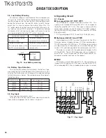
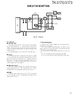
2-tone
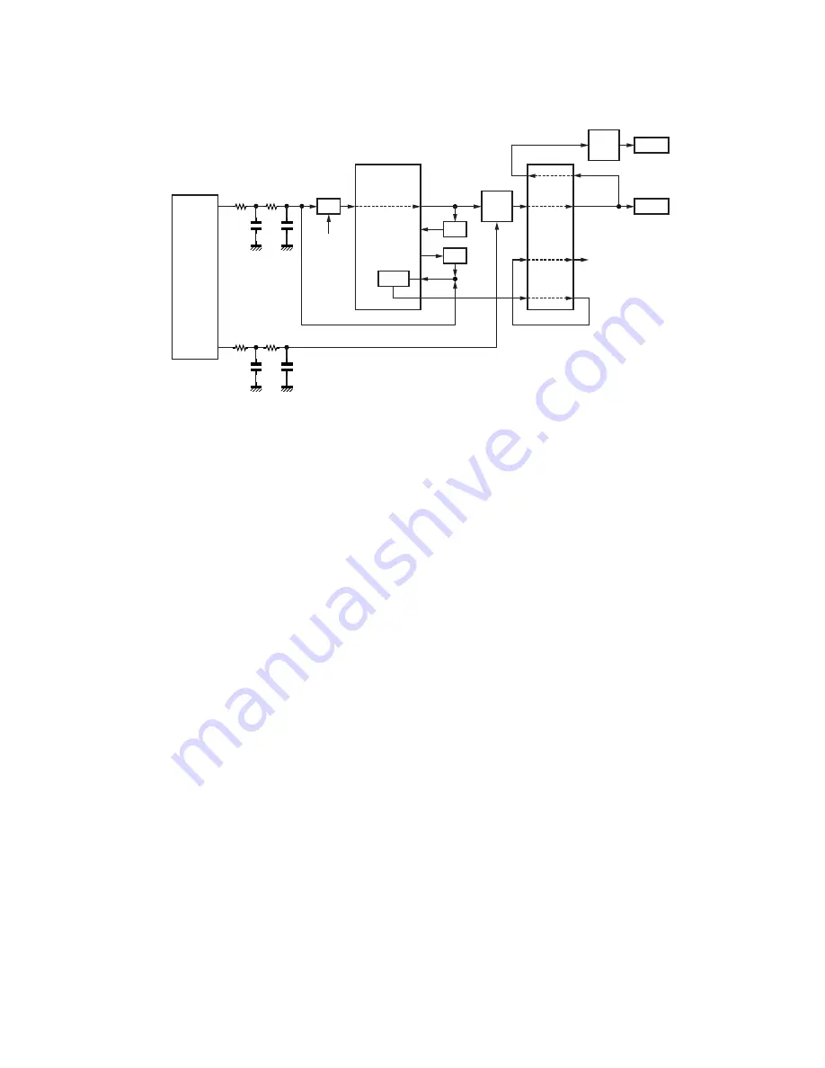
Part of the received AF signal output from the AF amplifier
IC10, and then passes through an audio processor (IC13),
goes to the other AF amplifier IC15, is compared, and then
goes to IC7. IC7 checks whether 2-tone data is necessary. If
it matches, IC7 carries out a specified operation, such as turn-
ing the speaker on. (See Figure 4)
■
MSK (Fleet Sync)
Fleet Sync utilizes 1200bps and 2400bps MSK signal is
output from pin 6 of IC13. And is routed to the VCO. When
encoding MSK, the microphone input signal is muted.
■
DTMF
The DTMF input signal from the IF IC (IC701) is amplified
by IC10 and goes to IC13. The decoded information is then
processed by the CPU.
SW
SW
SW
SUM
BUFF
AMP
MOD
AMP
VCO
TCXO
RXAF
MOD
6
5
4
EXTLIMIN
RX Audio
IC14
IC17 (1/2)
I2
O2
O8
I8
I4
O4
I3
O3
AF AMP
IC16
IC13
AQUA-L
HSDO
IC7
CPU
30
LSDO
IC12
7. Power Supply
There are five 5V power supplies for the microprocessor:
5M, 5MS, 5C, 5R and 5T.
5M is always output while the power is on. 5M is always
output, but turns off when the power is turned off to prevent
malfunction of the microprocessor.
5C is a common 5V and is output when SAVE is not set to
OFF.
5R is 5V for reception and output during reception.
5T is 5V for transmission and output during transmission.
Fig. 12
Encode


