2
TK-760/G
(
N
)
/762G/
(
N
)
CONTENTS / GENERAL
GENERAL
INTRODUCTION
SCOPE OF THIS MANUAL
This manual is intended for use by experienced techni-
cians familiar with similar types of commercial grade com-
munications equipment. It contains all required service in-
formation for the equipment and is current as of the publica-
tion date. Changes which may occur after publication are
covered by either Service Bulletins or Manual Revisions.
These are issued as required.
ORDERING REPLACEMENT PARTS
When ordering replacement parts or equipment informa-
tion, the full part identification number should be included.
This applies to all parts : components, kits, or chassis. If the
part number is not known, include the chassis or kit number
of which it is a part, and a sufficient description of the re-
quired component for proper identification.
PERSONNEL SAFETY
The following precautions are recommended for person-
nel safety :
• DO NOT transmit if someone is within two feet (0.6
meter) of the antenna.
• DO NOT transmit until all RF connectors are verified se-
cure and any open connectors are properly terminated.
• SHUT OFF and DO NOT operate this equipment near
electrical blasting caps or in an explosive atmosphere.
• All equipment should be properly grounded before
power-up for safe operation.
• This equipment should be serviced by a qualified techni-
cian only.
Note
The terms, “Wide” and “Semi wide” this service
manual, are same as “W5k” and “W4k” in the KPG-67D
(Field Programming Unit) menu and help text, respectively.
PRE-INSTALLATION CONSIDERNATIONS
1. UNPACKING
Unpack the radio from its shipping container and check
for accessory items. If any item is missing, please contact
KENWOOD immediately.
CONTENTS
GENERAL ................................................................. 2
SYSTEM SET-UP ..................................................... 4
OPERATING FEATURES ......................................... 5
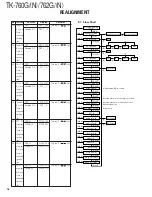
REALIGNMENT ...................................................... 11
INSTALLATION ...................................................... 18
CIRCUIT DESCRIPTION ......................................... 24
SEMICONDUCTOR DATA ..................................... 29
DESCRIPTION OF COMPONENTS ....................... 31
PARTS LIST ............................................................ 33
EXPLODED VIEW .................................................. 42
PACKING ................................................................ 44
ADJUSTMENT ....................................................... 45
PC BOARD VIEWS
DISPLAY UNIT (X54-3270-10) : TK-760G ........ 54
DISPLAY UNIT (X54-3280-10) : TK-762G ........ 55
PLL/VCO (X58-4670-10) ................................... 56
TX-RX UNIT (X57-595X-XX) (A/2) ................... 57
TX-RX UNIT (X57-595X-XX) (B/2) ................... 63
SCHEMATIC DIAGRAM ........................................ 67
BLOCK DIAGRAM .................................................. 75
LEVEL DIAGRAM ................................................... 78
TERMINAL FUNCTION ......................................... 80
SPECIFICATIONS ................................................... 81


