32
TK-760G/
(
N
)
/762G/
(
N
)
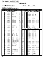
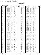
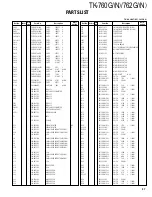
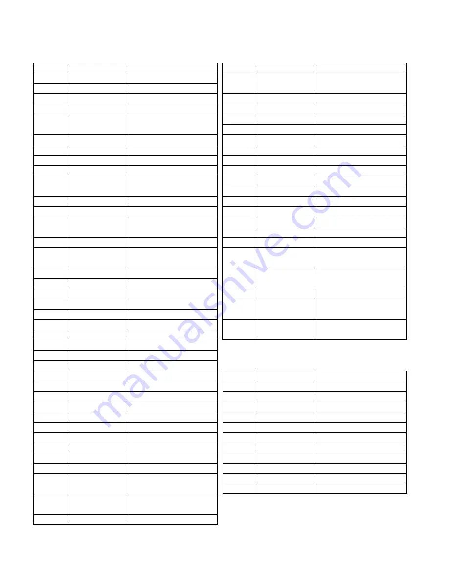
DESCRIPTION OF COMPONENTS
Ref. No.
Use/Function
Operation/Condition
IC10
5V AVR
5C (TX/RX)
IC11
9V AVR
9C
IC12
8V AVR
8C
IC13
AF amplifier
IC14
Power supply logic
circuit control
IC15
DC amplifier
APC control
IC400
Power module
IC501
Flash ROM
IC502
CPU
IC503
Reset IC
Low voltage output when
powering up
IC505
EEPROM
IC507
Amplifier
MIC, AFO
IC508
Audio processor
Compander, MIC amplifier,
ALC, AF filter, IDC
IC509
Analog switch
MO, DEO, EMG, MI switch
IC510
Shift/Store register
W/N, MM2, MBL, LED0, LED1,
AFREG1, AFREG2, BSHIFT
IC511
DTMF decode
IC512
5V AVR
5C (control)
IC513
Amplifier
QT/DQT decode
IC514
Amplifier
2-Tone and 5-tone decode
Q1
DC switch
HOR
Q2
DC switch
5S
Q5
DC switch
HNC
Q6
DC switch
IGN
Q7
Buffer amplifier
16.8MHz x 3
Q8
Lipple filter
8CL
Q9
Buffer amplifier
PLL fin
Q10
Noise amplifier
Squelch
Q11
Charge pump
øP
Q12
Charge pump
øR
Q13
IF amplifier
49.95MHz
Q14
Buffer amplifier
Hetetodyne
Q15
Mixer
Q16
DC switch
8R cont, active while RX
Q17
AF mute
Active while AF mute
Q18
DC switch
8R, active while RX
Q19,20
DC switch
SB switch, active when
powering up
Q21
DC switch
Active while PS voltage is more
than 20V
Q22
RF amplifier
Predrive
Ref. No.
Use/Function
Operation/Condition
Q23
DC switch
SB switch, active when
powering up
Q24
AF mute
Active while power switch is off
Q25
RF amplifier
Drive
Q26
Inverter
Active while power switch is low
Q27
L.N.A.
Q28
DC switch
8T, active while TX
Q29
DC switch
8T cont, active while TX
Q31
APC controller
Q32
APC controller
DB
Q33
APC controller
Power protection
Q36
DC switch
Power protection
Q37
AF mute switch
Inactive on mute
Q38
DC switch
5S
Q39
DC switch
Output enable
Q501
Clock switch shift
Clock shift is on while BSHIFT is H
Q502
AF mute
Active while MUTE is H
Q503
Inverter
Active while PA2 is H,
active while public address
Q504
LED switch (Red)
Active while LED0 is H,
active while TX
Q505,506
Key backlight switch
Active while MBL is H
Q508
LED switch (Green)
Active while LED1 is H,
active while RX
Q509
MIC mute
Active while MM is H and
MM2 is H
PLL/VCO (X58-4670-10)
Ref. No.
Use/Function
Operation/Condition
D101
RX VCO
D102
TX VCO
D103
RX VCO
D104
TX VCO
D105
Modulation
Q101
Oscillator
RX
Q102
Inverter
Active while ST is H
Q103
Oscillator
TX
Q104
TX/RX switch (TX)
Active while ST is H
Q105
TX/RX switch (RX)
Active while Q102 is off
Q106
Buffer amplifier


