4
TK-782
SERVICE
This radio is designed for easy servicing. Refer to the
schematic diagrams, printed circuit board views, and align-
ment procedures contained in this manual.
Note
When you modify your radio as described in system set-
up, take the following precaution.
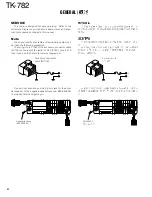
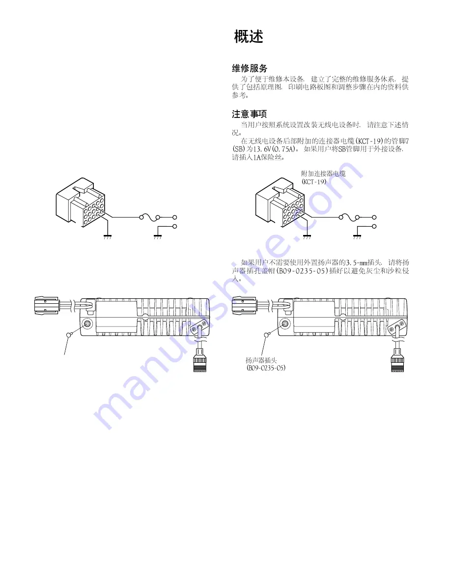
The rating of pin 7 (SB) of the accessory connector cable
(KCT-19) on the rear of the radio is 13.6V (0.75A). Insert a 1A
fuse if you use the SB pin for external equipment.
Accessory connector
cable (KCT-19)
If you do not intend to use the 3.5-mm jack for the exter-
nal speaker, fit the supplied speaker-jack cap (B09-0235-05)
to stop dust and sand getting in.
1
3
+
7
6
13
15
Speaker-jack cap
(B09-0235-05)
1
3
+
7
6
13
15
GENERAL /
Summary of Contents for TK-782
Page 64: ...TK 782 1 8 1 BLC 2 PSB 3 E 4 PTT 5 ME 6 MIC 7 HOOK 8 CM 63 ...
Page 68: ...TK 782 67 ...
Page 70: ...TK 782 69 ...
Page 72: ...TK 782 71 ...
Page 74: ...TK 782 73 ...
Page 76: ...TK 782 75 ...
Page 78: ...TK 782 77 ...


