60
TK-782
!
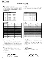
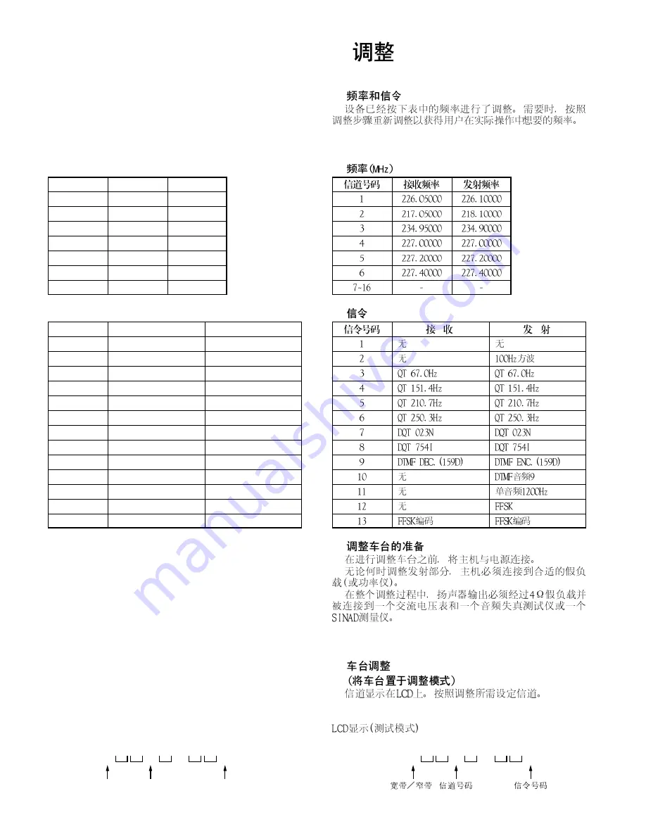
Frequency and Signalling
The set has been adjusted for the frequencies shown in
the following table. When required, re-adjust them following
the adjustment procedure to obtain the frequencies you want
in actual operation.
"
Frequency (MHz)
Channel No.
RX
TX
1
226.05000
226.10000
2
217.05000
218.10000
3
234.95000
234.90000
4
227.00000
227.00000
5
227.20000
227.20000
6
227.40000
227.40000
7~16
-
-
"
Signalling
Signalling No.
RX
TX
1
None
None
2
None
100Hz square
3
QT 67.0Hz
QT 67.0Hz
4
QT 151.4Hz
QT 151.4Hz
5
QT 210.7Hz
QT 210.7Hz
6
QT 250.3Hz
QT 250.3Hz
7
DQT 023N
DQT 023N
8
DQT 754I
DQT 754I
9
DTMF DEC. (159D)
DTMF ENC. (159D)
10
None
DTMF tone 9
11
None
Single tone 1200Hz
12
None
FFSK
13
FFSK code
FFSK code
!
Preparations for tuning the transceiver
Before attempting to tune the transceiver, connect the unit
to a suitable power supply.
Whenever the transmitter is turned, the unit must be con-
nected to a suitable dummy load (i.e. power meter).
The speaker output connector must be terminated with a
4
Ω
dummy load and connected to an AC voltmeter and an
audio distortion meter or a SINAD measurement meter at all
times during tuning.
!
Transceiver tuning
(To place transceiver in tuning mode)
Channel appears on LCD. Set channel according to tun-
ing requirements.
LCD display (Test mode)
!
"
"
!
!
ADJUSTMENT /
1
n
1
Channel No.
W/N
Signalling No.
1
n
1
Summary of Contents for TK-782
Page 64: ...TK 782 1 8 1 BLC 2 PSB 3 E 4 PTT 5 ME 6 MIC 7 HOOK 8 CM 63 ...
Page 68: ...TK 782 67 ...
Page 70: ...TK 782 69 ...
Page 72: ...TK 782 71 ...
Page 74: ...TK 782 73 ...
Page 76: ...TK 782 75 ...
Page 78: ...TK 782 77 ...


