19
TK-785
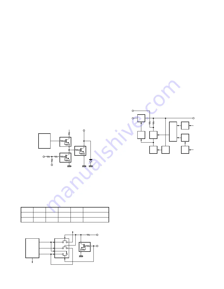
Q27
SW
Q28
SW
Q30
SW
Q25
SW
Q22
SW
Q26
INV.
IC15
F.F.
Q31
SW
D34
SW
R152
R151
IGN
SB
+B
PSW
TOF
IC7
6pin
Fig. 16
Power supply circuit
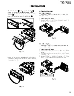
8C
HOR
D7
Q4
Q6
R58
Q5
R2
R50
R152
+B
IC7
Shift
register
HNC
IGN
Fig. 14
Horn control
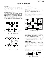
SW.D
SW.B
SW.A
TXOUT
MSKGS
RXIN
IC504
Audio
processor
RXOUT
IC506
Analog
SW
MO
47K
Q507
5C
“PA2”
Fig. 15
PA switch
■
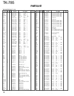
D/A Converter
The D/A converter (IC5) is used to adjust TONE and MO
modulation, beep, AF volume, TV voltage, FC reference volt-
age, and PC POWER CONTROL voltage level.
Adjustment values are sent from the CPU as serial data.
The D/A converter has a resolution of 256 and the following
relationship is valid:
D/A output = (Vin – VDAref) / 256 x n + VDAref
Vin: Analog input
VDAref: D/A reference voltage
n: Serial data value from the microprocessor (CPU)
■
Horn Control
The horn switch, consisting of Q4, Q5, and Q6, controls
the horn relay. It is supplied by the dealer to provide the
external horn alert function.
Q5 disables horn alert, turning on when its base is high,
to inhibit the function. Normally, the output from IC7 is low,
and Q6 is off; the base of Q4 is about 0V and Q4 is off.
When horn alert is enabled, the output from IC7 goes high
and Q6 turns on. The base current flows through R58 to Q4
to turn Q4 on. Q4 can sink a maximum of 100mA. If the
operational KAP-1 is used, it can drive up to 2A.
■
PA Switch
If the optional KAP-1 is used, the PA (Public Address)
function becomes available. In this case, the signal flow
changes as follows;
“PA2”
Q507
SW.A
SW.B
SW.D
Public address
L
L
L
H
H
OFF
H
H
H
L
L
ON
CIRCUIT DESCRIPTION
Power Supply Circuit
When the POWER switch on the control unit is pressed,
the PSW signal goes low. This signal is inverted by Q26 and
sent to a flip-flop IC (IC15). This IC outputs a control signal
when the PSW goes low. When the power turns on, pin 1 of
IC15 outputs a low signal and Q30 turns on. The base of
Q28 goes high, Q28 turns on, SB SW (Q27) turns on and
power (SB) is supplied to the set.
This circuit has an over-voltage protection circuit. If a DC
voltage of 20V or higher is applied to the power cable, D34
turns on and a voltage is applied to the base of Q31. This
voltage turns Q31 on and turns Q28 and SBSW off. This
circuit has a TIMED POWER OFF (TOF) function which can
be programmed by software.
It is controlled through pin 6 of IC7. When the TOF line
goes high, Q22 turns on and then Q25 turns on. Pin 6 of
IC15 goes high, then pin 1 goes high to turn Q27 off.


