background image

21

TK-785

SEM

I

CONDUCTOR DATA

Terminal function (TX-RX unit IC8)

Pin No.

Port

Name

Function

1

STB

ES

Strobe

2

SI

DT

DATA

3

CLK

CK

Clock

4

Q1

AM1

Audio mute 1.  H : Mute, L : Unmute

5

Q2

LOK

No function

6

Q3

STR

VCO shift switching.  H : TX, L : RX

7

Q4

DM

Dead mute.  H : RX, L : TX

8

VSS

GND

9

QS

IC7 data output

10

NC

11

Q8

SQ

No function

12

Q7

CODE2

Option board data 2.  H : ON, L : OFF

13

Q6

CODE1

Option board data 1.  H : ON, L : OFF

14

Q5

OPT

Option board control.

H : ON, L : OFF / Auxiliary B.

15

OE

Output

16

VDC

+5V.

Power Module

M68729 (TX-RX Unit IC400) : K,E type

Equivalent circuit diagram

2

1

3

4

5

Terminal function (TX-RX unit IC7)

Pin No.

Port

Name

Function

1

STB

ES

Strobe

2

SI

DT

Data

3

CLK

CK

Clock

4

Q1

HORN

Horn alert.  H : ON, L : OFF /

Auxiliary A.  H : ON, L : OFF

5

Q2

HL

RF power switching.  H : High, L : Low

6

Q3

TIMOFF

Timed power off.  H : Power off

7

Q4

CODE3

Option board data 1.  H : ON, L : OFF

8

VSS

GND

9

NC

10

NC

11

Q8

W/N

No function

12

Q7

NC

13

Q6

PA1

Public address 1.  H : ON, L : OFF

14

Q5

CODE4

Option board data 1.  H : ON, L : OFF

15

OE

Output enable

16

VDC

+5V

Shift Register : BU4094BCFV

Terminal function (TX-RX unit IC508)

Pin No.

Port

Name

Function

1

ES

ES1

Strobe

2

DT

DAT

Data

3

CK

Clock

4

Q1

LEDR

Red LED.  H : ON, L : OFF

5

Q2

LEDG

Green LED.  H : ON, L : OFF

6

Q3

KEYBLT

Key back light.  H : ON, L : OFF

7

Q4

MMUTE

MIC mute.  H: Mute, L : Unmute

8

VSS

GND

9

NC

10

NC

11

Q8

PA2

Public address control 2.  H : ON, L : OFF

12

Q7

BSHIFT

Beat shift.  H : ON, L : OFF

13

Q6

KEY

TX power switching.  H : TX, L : RX

14

Q5

T/R

TX/RX switching.  H : RX, L : TX

15

OE

Output enable

16

VDC

+5V

1 : Input terminal (Pin)
2 : First power terminal (Vcc1)
3 : End power terminal (Vcc2)
4 : Output terminal (Pout)
5 : Fin (Earth)

Summary of Contents for TK-785

Page 1: ...ST 25 EXPLODED VIEW 40 PACKING 41 ADJUSTMENT 43 TERMINAL FUNCTION 51 PC BOARD VIEWS PLL VCO X58 471X XX 52 TX RX UNIT X57 6142 71 A 2 53 TX RX UNIT X57 6142 71 B 2 59 TX RX UNIT X57 6150 21 A 2 63 TX RX UNIT X57 6150 21 B 2 69 SCHEMATIC DIAGRAM 73 LEVEL DIAGRAM 89 BLOCK DIAGRAM 93 SPECIFICATIONS 99 CONTENTS Cabinet Upper A01 2165 13 Cabinet Lower A01 2166 13 Modular jack E08 0877 05 Panel assy A62...

Page 2: ...before installation 2 2 Testing The radio should be tested complete with all cabling and accessories as they will be connected in the final installa tion Transmitter frequency deviation and power output should be checked as should receiver sensitivity squelch operation and audio output QT equipment operation should be verified 3 PLANNING THE INSTALLATION 3 1 General Inspect the vehicle and determi...

Page 3: ...for external equip ment Accessory connector cable KCT 19 If you do not intend to use the 3 5 mm jack for the exter nal speaker fit the supplied speaker jack cap B09 0235 05 to stop dust and sand getting in GENERAL OPERATING FEATURES Speaker jack cap B09 0235 05 1 3 7 6 13 15 OPERATING FEATURES 1 Transceiver Controls and Indicators Fig 1 1 1 The Basics Features listed in this section are available ...

Page 4: ...10 D key Default setting None Press to activate its auxiliary function below Also press to scroll right while viewing stack entries 11 CALL key Press to call the displayed call address Display displays the strength of received signals the output power high or low status numbers and received call types appears when a control channel is found It flashes while the transceiver is searching for a contr...

Page 5: ...or example to hard disk first then use it 5 5 Programming With IBM PC If data is transferred to the transceiver from an IBM PC with the KPG 62D the destination data basic radio informa tion for each set can be modified Normally it is not neces sary to modify the destination data because their values are determined automatically when the frequency range fre quency type is set The values should be m...

Page 6: ...the display returns to PROG 57600 3 If you press the D switch while the version is dis played the checksum is displayed If you press the D switch again while the checksum is displayed the version is redisplayed Note Normally write in the high speed mode 3 4 5 6 7 8 9 INSTALLATION 1 Accessory Connection Cable KCT 19 Option The KCT 19 is an accessory connection cable for con necting external equipme...

Page 7: ...onnected to CN2 and A 15 when connector E is connected to CN2 are changed as described in the jumper chart 2 The functions of A 13 A 14 and A 15 are changed if the con nector E is connected to CN2 or CN4 of the radio No CN2 CN4 E 1 LOK AM LOK E 2 MM RXD E 3 LOK DTC TXS FSW TXD Connect CN6 of the radio to connector C of the KCT 19 instead of to the internal speaker connector if use external speaker...

Page 8: ...IC mute input 3 DTC I No function TXS O No function FSW I Foot switch signal input Foot sw on L Foot sw off H LOK O No function CN3 1 HOR O Horn alert signal output Signal output for horn relay drive open collector L level during horn drive Max sink current 100mA L level when AUX A is on 2 E Earth 3 SB O Power output after power switch DC 13 2V E 13 6V K M 15 0 75A max CN4 1 LOK O No function 2 RX...

Page 9: ...X audio output TXAO Control LOK O No function LOK TX RX OPT O Option board select OP TX RX CODE1 O Option code 1 for voice C1 TX RX scrambler code 1 CODE2 O Option code 1 for voice C2 TX RX scrambler code 2 CODE3 O Option code 1 for voice C3 TX RX scrambler code 3 CODE4 O Option code 1 for voice C4 TX RX scrambler code 4 SQ O No function SQ TX RX TXD1 O Serial data output 1 TD1 TX RX RXD1 I Serial...

Page 10: ...n when KCT 18 is connected R151 R152 KCT 18 cannot be connected Enable Enable Power on off and Horn Alert or Disable Enable AUX A on off Horn Alert or AUX A on off Timed power off Enable Disable Power cannot be turned on Disable Disable Table 1 R151 and R152 setup chart 5 Optional Voice Scrambler Function You can use the voice scrambler in the following two configurations 1 Assign this function to...

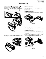
Page 11: ...nit board to the chassis with a screw The notch in the board must be placed at the front left side 4 Attach the cushion on the top of the KAP 1 switch unit 1 3 2 Fig 9 2 3 4 1 3 W1 W2 CN1 CN2 KCT 19 Cushion G13 1710 04 CN3 CN7 1 CN3 MPTT GND SB TXAO TXAI RXAO RXAI R571 R529 C4 C3 OP C2 C1 TX RX unit A 2 Component side view Control unit B 2 Foil side view Fig 7 Code 4 C4 Code 3 C3 Code 2 C2 Code 1 ...

Page 12: ... 1 and switches the audio power amplifier output between the external PA system through KCT 19 and internal and external speakers To use the PA function R109 on the TX RX unit must be removed R109 Use the PA function No Do not use the PA function Yes Fig 11 R1 Fig 10 KAP 1 foil side view 6 2 Modifying the Transceiver Horn alert The signal from pin 4 of IC7 on the TX RX unit turns Q4 and Q6 on and ...

Page 13: ...rminal into the square plug supplied with the KCT 19 3 Connect CN5 of the transceiver to connector C of the KCT 19 instead of to the internal speaker connector KES 4 1 3 6 13 15 12 Crimp terminal E23 0613 05 Black lead Black White lead Fig 16 6 Rotate the control panel 180 degrees and mount it on the transceiver Refit the two halves of the case to complete installation Fig 14 Fig 14 INSTALLATION 1...

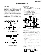
Page 14: ...s a mixer to achieve a high potential The signal output from the mixer passes through two MCFs XF1 The signal is amplified by an intermediate fre quency amplifier and input to the FM IF IC IC11 The first intermediate frequency signal is mixed with the second local signal of 44 395MHz to produce the second IF signal of 455kHz The unwanted near by signal components are then elimi nated by a ceramic ...

Page 15: ...C3 Q103 IC711 MIC AF AMP TA75S01F MIC KEY INPUT AF AMP IDC LPF TC35453F IC511 CPU 30620M8 394GP SUM AMP TA75W558FU X1 VCXO 16 8MHz VCO 2SK508NV K53 IC300 PLL SA7025DK Q106 RF AMP 2SC4215 Y Q300 BUFFER 2SC4215 Y Q203 RF AMP 2SC3357 Q204 ANT RF AMP 2SC2954 IC400 POWER AMP M68729 Q7 BUFFER 2SC4215 Y Fig 5 Transmitter system K E type CIRCUIT DESCRIPTION LPF ANT L203 BPF L207 BPF Q201 AMP Q15 AMP IC2 A...

Page 16: ...nd a voltage is applied to 8T The CPU in the control unit monitors the PLL IC300 LD signal directly When the KEY signal goes low no voltage is applied to 8T and no signal is transmitted nal is compared with the reference frequency which is out put from the VCXO X1 VCXO provides 16 8MHz 2 5ppm 30 to 60 C and guarantees stable performance when the temperature changes The output signal from the phase...

Page 17: ...AFDAT AFRDT AFTRD AFRTM AFSTB IC504 Audio processor IC507 DTMF DECO IC511 CPU TX RX UNIT LCD ASSY Fig 8 Control circuit RF AMP Q203 RF AMP Q204 POWER AMP IC400 APC DRIVER Q19 DB B VR1 Q20 PRI DRIVER DC AMP IC6 PC SW Q17 ANT SW D211 LPF ANT Q29 POWER DET D27 30 Q21 APC CONTROL H L SW H L IC7 5pin 15W E High power 10W K High power H 8T TX 8V TX PC SW ON D15 PC IC5 23pin Fig 7 APC circuit K E type RF...

Page 18: ... 3 MO of IC5 and the resulting signal goes to the MD pin of the VCO This signal is applied to a varicap diode in the VCO for direct FM modulation X1 VCXO IC5 D A A1 VCO IC3 SUM AMP IC506 Analog SW IC504 Audio processor IC300 PLL MB MD MO TO HT DI MIC TX RX UNIT AFDAT LSDO HSDO IC511 CPU Fig 12 Encode Q512 SW Q508 SW Q509 SW Q513 SW KBLC LG LR IC508 Shift register D511 GRN RED D512 517 LEDA Fig 10 ...

Page 19: ...en horn alert is enabled the output from IC7 goes high and Q6 turns on The base current flows through R58 to Q4 to turn Q4 on Q4 can sink a maximum of 100mA If the operational KAP 1 is used it can drive up to 2A PA Switch If the optional KAP 1 is used the PA Public Address function becomes available In this case the signal flow changes as follows PA2 Q507 SW A SW B SW D Public address L L L H H OF...

Page 20: ... I PLL unlock detect input 32 AFMSKE O FFSK modulation enable Enable active H 33 TXD O Serial interface output 34 HOOK I Hook input Serial interface input 35 AFDAT O FFSK data output Microprocessor 30620M8 394GP TX RX Unit IC511 Pin No Name I O Function 36 RFCLK O Common clock output TX RX unit 37 RDY Not used 38 ALE Not used 39 HOLD Not used 40 HLDA Not used 41 BLCK Not used 42 RD Flash memory RD...

Page 21: ...L OFF Auxiliary A H ON L OFF 5 Q2 HL RF power switching H High L Low 6 Q3 TIMOFF Timed power off H Power off 7 Q4 CODE3 Option board data 1 H ON L OFF 8 VSS GND 9 NC 10 NC 11 Q8 W N No function 12 Q7 NC 13 Q6 PA1 Public address 1 H ON L OFF 14 Q5 CODE4 Option board data 1 H ON L OFF 15 OE Output enable 16 VDC 5V Shift Register BU4094BCFV Terminal function TX RX unit IC508 Pin No Port Name Function...

Page 22: ...tive while TX Q18 DET mute Active while KEY is H Q19 APC APC driver Q20 APC APC predriver Q21 APC control Q22 TOF switch Active while TOF is H DESCRIPTION OF COMPONENTS Ref No Use Function Operation Condition Q23 W N switch No function Q24 W N switch No function Q25 TOF switch Active while Q22 is on Q26 Inverter Active while power switch is L Q27 SB switch Active while Q28 is on Q28 SB SW control ...

Page 23: ...e KEY is H Q19 APC APC driver Q20 APC APC predriver Q21 APC control Q22 TOF switch Active while TOF is H DESCRIPTION OF COMPONENTS Ref No Use Function Operation Condition Q23 24 W N switch No function Q25 TOF switch Active while Q22 is on Q26 Inverter Active while power switch is L Q27 SB switch Active while Q28 is on Q28 SB SW control Active while Q30 is on and Q31 is off Q29 H L switch Active wh...

Page 24: ...Clock shift is on while BSFT is H Q511 FSW swtich Foot switch is on while FSW is L Q512 513 Key backlight switch Active while KBLC is H Q515 Key backlight switch Active while KBLC is H D501 Surge absorption BLC D502 Over current PSB protection D503 Surge absorption CM D504 Surge absorption PTT TXD D505 Surge absorption HOOK RXD D507 OR gate MIC mute MM MM1 D508 Limiter MIC D509 Limiter ASQ D510 Re...

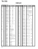
Page 25: ...2 02 KEY TOP A 1A 2A N33 2606 45 OVAL HEAD MACHINE SCREW B 2C N67 3008 46 PAN HEAD SEMS SCREW C 2B 1C N87 2606 46 BRAZIER HEAD TAPTITE SCREW D 2B N87 2612 46 BRAZIER HEAD TAPTITE SCREW 47 1D 1F N99 0395 05 SCREW SET 49 1B T07 0246 05 SPEAKER 51 1F T91 0624 05 MIC ASSY ACC E D511 B30 2151 05 LED TX BUSY D512 517 B30 2171 05 LED C1 15 CK73GB1H102K CHIP C 1000PF K C16 C92 0507 05 CHIP TAN 4 7UF 6 3WV...

Page 26: ... 1000PF K C145 146 CK73GB1H471K CHIP C 470PF K C147 CC73FCH1H0R5B CHIP C 0 5PF B C148 CK73GB1H102K CHIP C 1000PF K C149 CC73FCH1H020B CHIP C 2 0PF B C150 CK73GB1H221K CHIP C 220PF K C151 CC73GCH1H820J CHIP C 82PF J C153 CC73GCH1H080D CHIP C 8 0PF D C154 155 CK73GB1E103K CHIP C 0 010UF K C156 CK73GB1C104K CHIP C 0 10UF K C157 CK73GB1E103K CHIP C 0 010UF K C161 CC73GCH1H101J CHIP C 100PF J C163 CC73...

Page 27: ... K C519 C92 0507 05 CHIP TAN 4 7UF 6 3WV C520 CC73GCH1H221J CHIP C 220PF J C521 522 CK73GB1C104K CHIP C 0 10UF K C523 CK73GB1H103K CHIP C 0 010UF K C524 CK73GB1C104K CHIP C 0 10UF K C525 CK73GB1H103K CHIP C 0 010UF K C526 CK73GB1C104K CHIP C 0 10UF K C527 CK73GB1C683K CHIP C 0 068UF K C528 CK73GB1H102K CHIP C 1000PF K C529 CK73GB1H562J CHIP C 5600PF J C531 CK73GB1H562J CHIP C 5600PF J C533 CK73GB1...

Page 28: ...E COIL L216 L34 4482 05 AIR CORE COIL L217 218 L34 0499 05 AIR CORE COIL L219 L40 2778 67 SMALL FIXED INDUCTOR 27NH L220 L40 1888 67 SMALL FIXED INDUCTOR 180NH L221 L40 2278 67 SMALL FIXED INDUCTOR 22NH L222 L40 6878 67 SMALL FIXED INDUCTOR 68NH L223 L40 3378 67 SMALL FIXED INDUCTOR 33NH L225 L92 0193 05 FERRITE CHIP L226 L92 0155 05 FERRITE CHIP L227 L40 1878 67 SMALL FIXED INDUCTOR 18NH L230 L40...

Page 29: ...W R139 R92 0670 05 CHIP R 0 OHM R140 R92 1252 05 CHIP R 0 OHM R141 RK73GB1J104J CHIP R 100K J 1 16W R142 R92 0699 05 CHIP R 10 J 1 2W R143 RK73GB1J102J CHIP R 1 0K J 1 16W R144 RK73GB1J223J CHIP R 22K J 1 16W R145 RK73GB1J104J CHIP R 100K J 1 16W R146 R92 1215 05 CHIP R 470 J 1 2W R147 RK73FB2A563J CHIP R 56K J 1 10W R148 RK73FB2A472J CHIP R 4 7K J 1 10W R149 RK73FB2A333J CHIP R 33K J 1 10W R150 R...

Page 30: ...K J 1 16W R529 R92 1252 05 CHIP R 0 OHM R530 RK73GB1J394J CHIP R 390K J 1 16W R531 RK73GB1J473J CHIP R 47K J 1 16W R532 RK73GB1J394J CHIP R 390K J 1 16W R533 R92 1252 05 CHIP R 0 OHM R535 RK73GB1J155J CHIP R 1 5M J 1 16W R536 RN73GH1J682D CHIP R 6 8K D 1 16W R537 538 RK73GB1J473J CHIP R 47K J 1 16W R540 RK73GB1J474J CHIP R 470K J 1 16W R541 RK73GB1J274J CHIP R 270K J 1 16W R542 RN73GH1J683D CHIP R...

Page 31: ...J 1 16W R721 RK73GB1J334J CHIP R 330K J 1 16W R722 RK73FB2A680J CHIP R 68 J 1 10W R723 R92 1252 05 CHIP R 0 OHM R724 RK73GB1J562J CHIP R 5 6K J 1 16W R725 RK73GB1J392J CHIP R 3 9K J 1 16W R726 R92 1252 05 CHIP R 0 OHM R727 RK73GB1J472J CHIP R 4 7K J 1 16W R730 RK73GB1J472J CHIP R 4 7K J 1 16W VR1 R32 0658 05 SEMI FIXED VARIABLE RESISTOR D1 6 DA204U DIODE D1 6 HSB123 DIODE D7 02DZ20 Y Z ZENER DIODE...

Page 32: ...47PF J C29 C92 0628 05 CHIP TAN 10UF 10WV C30 CK73GB1H102K CHIP C 1000PF K C31 C92 0628 05 CHIP TAN 10UF 10WV C32 CC73GCH1H220J CHIP C 22PF J C33 CK73GB1E103K CHIP C 0 010UF K C34 C92 0505 05 CHIP TAN 10UF 16WV C35 CK73GB1E103K CHIP C 0 010UF K C36 C92 0628 05 CHIP TAN 10UF 10WV C37 C92 1341 05 ELECTRO 100UF 16WV C38 C92 0505 05 CHIP TAN 10UF 16WV C39 CK73GB1E103K CHIP C 0 010UF K C40 CK73GB1H102K...

Page 33: ...B1H102K CHIP C 1000PF K C207 CK73GB1H102K CHIP C 1000PF K C208 CC73GCH1H270J CHIP C 27PF J C209 CC73GCH1H220J CHIP C 22PF J C210 CC73GCH1H010C CHIP C 1 0PF C C211 212 CK73GB1H471K CHIP C 470PF K C213 CC73GCH1H010C CHIP C 1 0PF C C214 CC73GCH1H180J CHIP C 18PF J C215 CK73GB1H471K CHIP C 470PF K C216 CK73GB1E103K CHIP C 0 010UF K C217 CK73GB1H102K CHIP C 1000PF K C218 CK73GB1H471K CHIP C 470PF K C22...

Page 34: ... CK73GB1C333K CHIP C 0 033UF K C553 CK73GB1H472K CHIP C 4700PF K C554 558 CK73GB1C104K CHIP C 0 10UF K C559 CK73GB1H102K CHIP C 1000PF K C560 C92 0507 05 CHIP TAN 4 7UF 6 3WV C561 CK73GB1H102K CHIP C 1000PF K C562 563 CK73GB1H472K CHIP C 4700PF K C564 CK73GB1E223K CHIP C 0 022UF K C565 CK73GB1H102K CHIP C 1000PF K C566 CC73GCH1H101J CHIP C 100PF J C567 CK73GB1C473J CHIP C 0 047UF J C568 C92 0712 0...

Page 35: ...CHIP R 1 0K J 1 16W R6 7 R92 1252 05 CHIP R 0 OHM R8 RK73GB1J102J CHIP R 1 0K J 1 16W R9 R92 1252 05 CHIP R 0 OHM R10 11 RK73GB1J102J CHIP R 1 0K J 1 16W R12 R92 1252 05 CHIP R 0 OHM R14 RK73GB1J473J CHIP R 47K J 1 16W R15 RK73GB1J103J CHIP R 10K J 1 16W R16 RK73GB1J473J CHIP R 47K J 1 16W R17 18 R92 1252 05 CHIP R 0 OHM R19 RK73GB1J153J CHIP R 15K J 1 16W R20 RK73GB1J104J CHIP R 100K J 1 16W R21 ...

Page 36: ...0K J 1 16W R170 R92 1252 05 CHIP R 0 OHM R176 R92 0670 05 CHIP R 0 OHM R181 182 R92 0679 05 CHIP R 0 OHM R200 R92 0670 05 CHIP R 0 OHM R205 R92 0670 05 CHIP R 0 OHM R209 210 RK73GB1J104J CHIP R 100K J 1 16W R211 RK73GB1J332J CHIP R 3 3K J 1 16W R212 213 RK73GB1J102J CHIP R 1 0K J 1 16W R214 RK73GB1J220J CHIP R 22 J 1 16W R215 RK73GB1J100J CHIP R 10 J 1 16W R217 218 RK73GB1J104J CHIP R 100K J 1 16W...

Page 37: ...3GB1J223J CHIP R 22K J 1 16W R552 RK73GB1J334J CHIP R 330K J 1 16W R553 RK73GB1J102J CHIP R 1 0K J 1 16W R554 RK73GB1J332J CHIP R 3 3K J 1 16W R555 RK73GB1J394J CHIP R 390K J 1 16W R556 RK73GB1J223J CHIP R 22K J 1 16W R558 R92 1252 05 CHIP R 0 OHM R562 RK73GB1J273J CHIP R 27K J 1 16W R564 R92 1252 05 CHIP R 0 OHM R566 RK73GB1J470J CHIP R 47 J 1 16W R567 RK73GB1J220J CHIP R 22 J 1 16W R568 RK73GB1J...

Page 38: ... 02DZ5 6 X Y ZENER DIODE D22 23 DAN235E DIODE D24 MINISMDC075 02 VARISTOR D26 1SS355 DIODE D27 HSM88AS DIODE D28 02DZ15 X Y ZENER DIODE D30 HSM88AS DIODE D31 1SS355 DIODE D32 22ZR 10D SURGE ABSORBER D34 02DZ18 X Y ZENER DIODE D35 MA742 DIODE D37 DSA3A1 DIODE D203 206 MA2S377 VARIABLE CAPACITANCE DIODE D207 HSB123 DIODE D209 MA4PH633 DIODE D210 211 XB15A709 DIODE D212 215 MA2S377 VARIABLE CAPACITAN...

Page 39: ... CK73GB1H102K CHIP C 1000PF K C129 CK73GB1H102K CHIP C 1000PF K C130 CC73GCH1H060B CHIP C 6 0PF B M C130 CC73GCH1H100D CHIP C 10PF D K E C131 CC73GCH1H040B CHIP C 4 0PF B M C131 CC73GCH1H050B CHIP C 5 0PF B K E C132 CC73GCH1H120J CHIP C 12PF J M C132 CC73GCH1H150J CHIP C 15PF J K E C133 134 CK73GB1H102K CHIP C 1000PF K C135 136 CC73GCH1H020B CHIP C 2 0PF B C138 CC73GCH1H150J CHIP C 15PF J C139 CK7...

Page 40: ... C 1 30 28 49 15 32 25x2 11 13 9 7 7 31 19 20 IC400 28 29x2 J501 22 6 45 14 27 30 2 30 3 17x2 K E only 33 J1 TX RX unit Control unit Cx2 703 701 702 B B Cx2 Dx11 18 Ax2 C C A A A M2 6 x 6 OC BLK N32 2606 45 B M3 x 8 N67 3008 46 C M2 6 X 6 Br Tap N87 2606 46 D M2 6 x 12 Br Tap N87 2612 46 21 M only ...

Page 41: ... 0103 04 5 Cap B09 0235 05 12 DC cord E30 3339 05 23 Fuse F51 0016 05 43 Bracket J29 0627 23 37 Inner packing case H12 1391 03 47 Screw set N99 0395 05 36 Polystyrene foamed fixture H10 6619 12 39 Protection bag H25 0720 04 8 Instruction manual B62 1262 00 35 Polystyrene foamed fixture H10 6618 12 40 Item carton case H52 1571 02 704 Warranty card K ...

Page 42: ... Bracket J29 0627 23 37 Inner packing case H12 1391 03 47 Screw set N99 0395 05 42 MIC hanger J19 1584 05 36 Polystyrene foamed fixture H10 6619 12 39 Protection bag H25 0720 04 8 Instruction manual B62 1262 00 35 Polystyrene foamed fixture H10 6618 12 40 Item carton case H52 1647 02 Parts with the exploded numbers larger than 700 are not supplied ...

Page 43: ...ift on Frequency and Signalling The set has been adjusted for the frequencies shown in the following table When required re adjust them follow ing the adjustment procedure to obtain the frequencies you want in actual operation Frequency MHz Channel No K E M RX TX RX TX 1 226 05 226 10 260 05 260 10 2 217 05 218 10 250 05 250 10 3 234 95 234 90 269 95 269 90 4 227 00 227 00 260 00 260 00 5 227 20 2...

Page 44: ... 10 255 05 255 10 C 226 05 226 10 260 05 260 10 H2 230 05 230 10 265 05 265 10 H 234 95 234 90 269 95 269 90 F R E Q 1 Adjustment item Adjustment 1 256 Tuning flow D B HPOW xxx D L HPOW xxx B D L2 HPOW xxx B D C HPOW xxx B D D H2 HPOW xxx B H HPOW xxx D B MAX xxx D L MAX xxx B D C MAX xxx B H MAX xxx D 5 point tuning ex RF power high 3 point tuning ex Maximum deviation FREQ xxx D HPOW xxx B LPOW x...

Page 45: ... through 30MHz 6 High Sensitivity Frequency Range 10Hz to 1000MHz Frequency Counter Frequency Stability 0 2ppm or less 7 Ammeter 20A 8 AF Volt Meter Frequency Range 50Hz to 10kHz AF VTVM Voltage Range 1mV to 10V 9 Audio Generator AG Frequency Range 20Hz to 20kHz or more Output 0 to 1V 10 Distortion Meter Capability 3 or less at 1kHz Input Level 50mV to 10Vrms 11 4Ω Dummy Load Approx 4Ω 10W or more...

Page 46: ...ng the TK 785 The jig facilitates the voltage check when the voltage on the component side TX RX unit is checked during repairs Measurement Test equipment Unit Terminal Adjustment Unit Parts Method Specifications Remarks Condition Item 1 PLL lock 1 Set test mode DVM TX RX TP1 PLL TC101 1 5V Receive 0 1V voltage CH CH3 Sig1 Power meter A 2 PTT OFF Receive TC102 1 5V Transmit PTT ON Transmit 2 CH CH...

Page 47: ...MOD 1 5kHz AG AF output 1V 4Ω 2 C SENS Adjust for SSG freq 226 05MHz K E maximum SINAD 260 05MHz M 3 H SENS Adjust for SSG freq 234 95MHz K E maximum SINAD 269 95MHz M 3 Squelch 1 Set test mode Squelch must be Select L SQL in tuning mode closed once SSG freq 217 05MHz K E Then adjust for 250 05MHz M squelch open point SSG output Sensitivity value of 12dB SINAD SSG MOD 1 5kHz 2 C SQL SSG freq 226 0...

Page 48: ...0 05MHz M SSG output 15dB SINAD level 2 SSG output OFF Squelch must be closed 7 QT check 1 Set test mode Check Squelch must be opened CH CH1 Sig5 SSG freq 226 05MHz K E 260 05MHz M SSG MOD INT 1kHz EXT 151 4Hz SSG system MOD DEV 1 85kHz SSG output 12dB SINAD level 2 CH CH1 Sig4 Squelch must be closed CH1 Sig6 CH1 Sig7 1 Frequency 1 Set test mode Power meter Rear ANT Check 226 1MHz 100Hz K E Select...

Page 49: ...wer check 1 Set test mode Power meter ANT Check 10W 1W 6A or less K CH CH1 Sig1 15W 1W 6A or less E CH2 Sig1 Ammeter DC IN 25W 1W 8A or less M CH3 Sig1 PTT ON 6 Modulation 1 Set test mode Power meter Rear ANT Make the de balance MIC input OFF Deviation panel modulation Select BAL in tuning mode meter waveform near L BAL Oscilloscope Deviation meter filter LPF 3kHz AF VTVM Front MIC HPF OFF AG pane...

Page 50: ... meter filter LPF 3kHz HPF OFF PTT ON 2 C QT PTT ON 3 H QT PTT ON 10 DQT 1 Set test mode 0 35kHz 50Hz deviation Select DQT in tuning mode L DQT Deviation meter filter LPF 3kHz HPF OFF PTT ON 2 C DQT PTT ON 3 H DQT PTT ON 11 DTMF 1 Set test mode 1 5kHz 0 1kHz deviation Select DTMF in tuning mode Deviation meter filter LPF 15kHz HPF OFF PTT ON 12 FFSK 1 Set test mode 1 5kHz 0 1kHz deviation Select F...

Page 51: ...al 25 EN DA converter enable signal 26 APTT No function 27 CP PLL clock 28 DTC No function 29 TXD Serial data 30 RXD Serial data 31 OE Serial data 32 FSW Foot switch signal 33 E Ground CN101 VCO TX RX Unit Pin No Name Function 1 ST Switched transmit input H Transmit 2 HT RF output 3 E Ground 4 9CL 9V input 5 8CL 8V input 6 MD Modulation input 7 CV Control voltage input CN501 Control Unit Pin No Na...

Page 52: ...134 C135 C136 C138 L106 Q104 Q105 Q106 Q101 C111 L105 C120 C125 R103 D109 C143 CN101 CV MD 8CL 9CL E HT ST J72 0732 02 C107 C106 C121 C103 C102 C117 C119 R110 C108 R102 C126 C115 L101 C105 R117 R106 R104 C113 R115 R113 L102 R114 R111 C130 D101 D102 R118 D104 C131 C132 C139 C142 D107 R119 R120 R121 TC101 TC102 L111 C109 L107 Q102 G S D G S D Q103 L103 C114 L104 R116 C110 R101 R107 C104 R108 R105 L1...

Page 53: ... R77 C75 D9 VR1 R127 R122 R179 C140 C401 R403 R402 R401 C402 C131 CN4 D12 D13 D8 C70 C319 R314 R313 C318 C314 C309 C307 C311 R310 C37 C306 C4 C8 C13 C5 C2 C3 C6 C9 C7 C90 C38 C41 C97 Q401 C125 C296 C312 R309 R121 C100 R129 R98 R58 Q302 Q301 R300 C36 C16 R302 R305 R303 R301 R2 R50 R68 L5 C316 R312 R323 R311 C48 C28 R30 R44 R414 R111 Q21 1 3 4 5 R55 C321 Q17 R80 C68 R76 G IC14 I O R85 10 C109 C112 R...

Page 54: ...7 IC1 4 1 5 8 IC9 I G O S D G C65 C120 C42 C80 IC6 1 4 8 5 C121 C78 C144 R69 L230 D20 D26 R39 Q12 R62 R106 PA R90 R130 R36 R408 R52 R28 R29 R131 R104 L3 C55 D23 R107 R31 R22 R140 R153 R26 R27 D15 C30 R34 Q22 Q25 Q29 Q9 C146 C148 C181 Q204 Q203 E C B E C B R147 D212 C237 D211 C255 C231 C235 C240 C241 C282 C243 C261 C274 C273 C251 IC400 1 2 3 4 D210 R223 C290 C289 C272 C271 R224 R230 R238 C242 R250 ...

Page 55: ...R45 R42 C73 C76 D16 R144 R406 R9 R151 R138 R146 L4 C69 L1 Q23 Q24 Q26 Q28 Q30 Q31 R157 C135 C138 C145 C141 C147 C139 C149 C209 C238 IC201 1 3 4 5 R229 C207 C208 C229 C230 C232 C279 C233 C277 C234 C278 C280 C281 C176 C236 C239 C288 C407 C406 C256 D209 L211 L212 Q202 B C E R211 R212 R213 R214 R217 R220 R221 R228 R231 R232 R233 R234 R236 R237 R240 L225 C124 C128 C134 C136 C29 C157 R154 C155 R162 R163...

Page 56: ...R719 R720 R721 R724 R725 CN501 1 10 Q501 CN502 33 1 L501 L502 L504 L505 L508 Q515 E 5C CS CK SID NC NC LEDA LEDK NC E FSW OE RXD TXD DTC CP APTT EN EP ES LD RSSI DT CK KEY 8C SB SB IGN AHK MI ME AFO MM DEO PSW 8R BEEP TO MO T R W N IC508 CM MIC PTT TXD PSB BLC D513 E ME HOOK RXD R682 C592 C583 IC501 1 1 4 4 5 5 8 8 C513 C535 IC503 R507 C518 IC502 D517 R517 C593 C511 R508 C527 C575 R545 R551 D512 D...

Page 57: ...5 S R Q P O N M L K J I H G F E D C B A 1 2 3 4 5 6 7 8 9 10 11 12 13 14 IC508 CM MIC PTT TXD PSB BLC D513 E ME HOOK RXD R682 C592 C583 IC501 1 1 4 4 5 5 8 8 C513 C535 IC503 R507 C518 IC502 D517 R517 C593 C511 R508 C527 C575 R545 R551 D512 D515 D516 R514 R510 R612 R572 1 8 9 16 C524 R525 R526 C506 R502 C574 D510 D520 R548 C540 C547 R552 R523 R531 Q511 C510 C710 C712 1 1 8 4 5 3 4 5 C714 IC710 R710...

Page 58: ...40 R115 C422 R417 C131 C272 C271 CN4 C230 R234 L228 R221 D206 D205 D204 D203 D214 D12 D13 D8 C70 C319 R314 R313 C318 C314 R310 C37 C306 IC14 C4 C8 C13 C5 C2 C3 C6 C9 C7 C90 C295 C444 C294 C38 C41 C97 C423 C125 C293 C312 R309 R121 C100 R224 C239 R129 R98 R58 Q302 Q301 R300 C36 C16 R302 R305 R303 R301 R2 R50 C204 R420 C207 R68 L5 R312 R323 R311 C48 R414 C28 R30 R44 C201 L200 R111 Q21 C321 B C E Q203...

Page 59: ...IC1 IC9 C65 C135 C253 C42 R90 IC6 C121 Q202 1 2 3 4 C250 C247 R239 C248 C252 C249 Q205 C148 C78 C144 R69 C35 D20 D26 R39 8C 5C 8T TR SB 8R DT ES 9C Q12 R62 R106 PA C197 C198 C195 C196 C80 R130 R36 R411 R406 C24 R52 R425 R28 R29 L212 TP4 R131 R104 R238 L3 C55 Q204 C251 D23 R107 R31 R22 R140 C134 R26 R27 R147 C138 C145 TV C67 R79 D15 C30 R34 R231 SP R181 R182 Q22 Q25 Q29 Q9 L205 X1 LD QAD TP3 DEO KE...

Page 60: ... IC13 R46 R41 Q7 R33 R37 L218 C123 R23 R20 R124 R126 R237 R241 R236 R223 R61 C62 R154 D31 R155 R244 R243 R240 L217 R260 R142 C104 C118 C92 C108 D22 R45 R42 C73 C76 D16 R144 R145 R153 R17 C29 R9 R151 R138 R146 C141 C147 C292 L4 C69 IC200 1 3 4 6 R53 C234 L1 R235 L216 C245 C139 C149 Q23 Q24 Q26 Q28 Q30 Q31 R157 R242 C136 C153 C154 C155 C156 C275 C284 C285 C286 L7 R158 R421 R162 R251 R168 C279 C157 L...

Page 61: ...719 R720 R721 R724 R725 CN501 1 10 Q501 CN502 33 1 L501 L502 L504 L505 L508 C629 Q515 E 5C CS CK SID NC NC LEDA LEDK NC E FSW OE RXD TXD DTC CP APTT EN EP ES LD RSSI DT CK KEY 8C SB SB IGN AHK MI ME AFO MM DEO PSW 8R BEEP TO MO T R W N IC508 CM MIC PTT TXD PSB BLC D513 E ME HOOK RXD R682 C592 C583 IC501 1 1 4 4 5 5 8 8 C513 C535 IC503 R507 C518 IC502 D517 R517 C593 C511 R508 C527 C575 R545 R551 D5...

Page 62: ...C D E F G H I J K L M N O P Q R S 1 2 3 4 5 6 7 8 9 10 11 12 13 14 IC508 CM MIC PTT TXD PSB BLC D513 E ME HOOK RXD R682 C592 C583 IC501 1 1 4 4 5 5 8 8 C513 C535 IC503 R507 C518 IC502 D517 R517 C593 C511 R508 C527 C575 R545 R551 D512 D515 D516 R514 R510 R612 R572 1 8 9 16 C524 R525 R526 C506 R502 C574 D510 D520 R548 C540 C547 R552 R523 R531 Q511 C510 C710 C712 1 1 8 4 5 3 4 5 C714 IC710 R710 R713 ...

Page 63: ...T R P N L J H F D B S Q O M K I G E C A 1 3 5 7 2 4 6 SCHEMATIC DIAGRAM TK 785 K E Note Components marked with a dot are parts of patterun 1 76 ...

Page 64: ...A C E G I K M O Q S B D F H J L N P R T 1 3 5 7 2 4 6 77 TK 785 K E SCHEMATIC DIAGRAM Note Components marked with a dot are parts of patterun 1 ...

Page 65: ...T R P N L J H F D B S Q O M K I G E C A 1 3 5 7 2 4 6 SCHEMATIC DIAGRAM TK 785 M Note Components marked with a dot are parts of patterun 1 84 ...

Page 66: ...A C E G I K M O Q S B D F H J L N P R T 1 3 5 7 2 4 6 85 TK 785 M SCHEMATIC DIAGRAM Note Components marked with a dot are parts of patterun 1 ...

Page 67: ...INAD are obtained measured by connecting SG to each point via a 0 01µF capacitor AF VTVM AF level obtained when the AF output level is adjusted for 0 45V 4Ω with the front panel AF VOL control Measured with AF voltmeter connected to the external speaker jack receiving a 53dBm SSG signal modulated at 1kHz DEV 1 5kHz X58 4712 71 Wattmeter by 50Ω 1 AG is set so that MIC input becomes 1 5kHz DEV at 1k...

Page 68: ...dBm 25dBm 25W SG input level for 12dB SINAD are obtained measured by connecting SG to each point via a 0 01µF capacitor AF VTVM AF level obtained when the AF output level is adjusted for 0 45V 4Ω with the front panel AF VOL control Measured with AF voltmeter connected to the external speaker jack receiving a 53dBm SSG signal modulated at 1kHz DEV 1 5kHz X58 4710 21 Wattmeter by 50Ω 1 AG is set so ...

Page 69: ...TK 785 TK 785 TK 785 BLOCK DIAGRAM K E 95 ...

Page 70: ...TK 785 TK 785 TK 785 96 BLOCK DIAGRAM M ...

Page 71: ...t 140 5 51 W x 40 1 58 H x 145 5 73 D mm inch 0 94kg 2 07 lbs RECEIVER RF Input Impedance 50Ω Sensitivity EIA 12dB SINAD 0 28µV Adjacent Channel Selectivity EIA 75dB K ETS 73dB M E Intermodulation Rejection EIA 70dB K ETS 70dB M E Spurious and Image Rejection EIA 85dB K ETS 80dB M 90dB E Audio Power Output 4W at 4Ω less than 10 distortion Channel Frequency Spread 18MHz K E 20MHz M TRANSMITTER RF P...

Page 72: ...y 75018 Paris France KENWOOD ELECTRONICS U K LIMITED KENWOOD House Dwight Road Watford Herts WD1 8EB United Kingdom KENWOOD ELECTRONICS EUROPE B V Amsterdamseweg 37 1422 AC Uithoorn The Netherlands KENWOOD ELECTRONICS ITALIA S p A Via G Sirtori 7 9 20129 Milano Italy KENWOOD IBERICA S A Bolivia 239 08020 Barcelona Spain KENWOOD ELECTRONICS AUSTRALIA PTY LTD A C N 001 499 074 16 Giffnock Avenue Nor...

Reviews: