9
TK-785
INSTALLATION
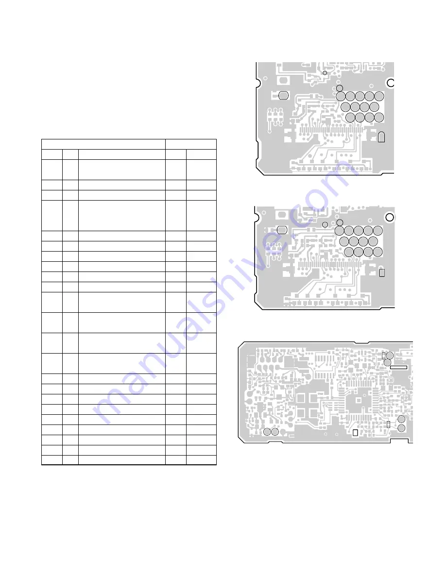
3. Optional Board Terminal
Terminal is for mounting the option board are provided at
the control and TX-RX unit. The table below shows the cor-
respondence between the board and terminals. Disconnect
R529 and R571 in control unit when the scrambler board is
attached.
The table below shown the differences between the
schematic terminals and the PC board terminals.
Schematic diagram
PC board view
Name
I/O
Function
Name
Unit
SB
O
Switched B+ (13.2V (E),
SB
TX-RX
13.6V (K,M), 0.75A)
5C
O
5C
5C
TX-RX
GND
–
Earth
E
TX-RX
DEO
O
Detect signal output (Output
DEO
TX-RX
level : 250mVrms; standard
modulation)
RXAI
I
RX audio input
RXAI
Control
RXAO
O
RX audio output
RXAO Control
TXAI
I
TX audio input
TXAI
Control
TXAO
O
TX audio output
TXAO
Control
LOK
O
No function.
LOK
TX-RX
OPT
O
Option board select.
OP
TX-RX
CODE1
O
Option code 1 (for voice
C1
TX-RX
scrambler code 1)
CODE2
O
Option code 1 (for voice
C2
TX-RX
scrambler code 2)
CODE3
O
Option code 1 (for voice
C3
TX-RX
scrambler code 3)
CODE4
O
Option code 1 (for voice
C4
TX-RX
scrambler code 4)
SQ
O
No function.
SQ
TX-RX
TXD1
O
Serial data output 1
TD1
TX-RX
RXD1
I
Serial data input 1
RD1
TX-RX
TXD2
O
Serial data output 2
TD2
TX-RX
RXD2
I
Serial data input 2
RD2
TX-RX
RSSI
O
Receive signal strength indication
RSSI
TX-RX
PTT
I
PTT
PTT
Control
MPTT
I
MIC PTT
MPTT Control
FSW
I
Foot switch input
FW
TX-RX
MPTT
PTT
TXAO
TXAI
RXAO
RXAI
R571
R529
RSSI
E
DEO RD2 5C C4 C3
OP
SQ
RD1
TD2
TD1 FW C2 C1
SB
LOK
TX-RX unit (A/2)
Foil side view
Control unit (B/2)
Foil side view
RSSI
SB
LOK
E
DEO RD2 5C C4 C3
OP
SQ
RD1
TD2
TD1 FW C2 C1
Fig. 4-1
K,E type
Fig. 4-2
M type
TX-RX unit (A/2)
Foil side view
Fig. 4-3


