background image

8

Voice Calls

Making a Voice Call

Select a call address using one of the following four methods:

i)

Select a call address from memory:

  Select your desired call address

using the

/

(control) keys if a call address has been stored in

the transceiver memory.

ii)

Use a pre-programmed key:

  Press key AB

C, or D

 to select a

call address if they have been pre-programmed with call addresses.

iii)

Select a call address from the stack:

  Use a received voice call from the

stack as a call address (refer to “Viewing the Stack”, on page 10).

iv)

Enter a call address using the microphone keypad:

  Enter your desired

call address using the microphone keypad (keys 0 ~ 9,

, and #).

Refer to the appendix {page 15} for the available dial strings and
control codes.

Initiate the call, depending on how you selected the call address.

iii, and iii (of step 1):

When selecting a call address from memory or the stack, press the CALL
key (or the microphone PTT switch if “PTT to Initiate Call” has been
programmed) to initiate the call.

iv (of step 1):

When using MPT1343 dialing, press the microphone # key to initiate the
call.

“Calling” appears on the display.

When the call is connected, a timer appears on the display.

The timer can be set up to either count up (increasing number) or count down
(decreasing number).

Press the microphone PTT switch to transmit; release it to receive.

The LED lights red while transmitting.

The 3-digit sub-display shows your transmit power.  A single triangle (

)

represents low power while dual triangles (

▲▲

) represents high power.

Press the       key to end the call.  If the call time expires before you press

the       key, the call will be automatically terminated.

“END” momentarily appears on the display before returning to the call address
of the call you just made.

Summary of Contents for TK-785

Page 1: ... B62 1262 00 K M E 09 08 07 06 05 04 03 02 01 00 KENWOOD CORPORATION INSTRUCTION MANUAL VHF FM TRANSCEIVER UHF FM TRANSCEIVER TK 785 TK 885 ...

Page 2: ... OPERATION OF UNLICENSED RADIO TRANSMITTERS WITHIN THE TERRITORIES UNDER GOVERNMENT CONTROL ILLEGAL OPERATION IS PUNISHABLE BY FINE AND OR IMPRISONMENT REFER SERVICE TO QUALIFIED TECHNICIANS ONLY SAFETY It is important that the operator is aware of and understands hazards common to the operation of any transceiver WARNING EXPLOSIVE ATMOSPHERES GASES DUST FUMES etc Turn OFF your transceiver while t...

Page 3: ...Auxiliary Functions 6 Display 7 Searching for a Control Channel 7 Voice Calls 8 Making a Voice Call 8 Receiving a Voice Call 9 Status Calls 9 Making a Status Call 9 Receiving a Status Short Data Message Call 10 Call Displays 10 Viewing the Stack 10 Call Diversions 11 Diverting Your Own Calls 11 Diverting Third Party Calls 11 CONVENTIONAL MODE 12 Key Functions 12 Display 12 Entering Conventional Mo...

Page 4: ... b a c e n o h p o r c i m y l n o E 5 8 7 K T X X 0 7 3 3 0 6 X 1 y l n o 3 K K 5 8 8 K T X X 7 9 5 0 1 9 T s w e r c s g n i p p a t f l e s h t i w r e g n a h e n o h p o r c i M e n o h p o r c i m a g n i n i a t n o c s t i k h t i w y l n o d e i l p p u s X X 4 8 5 1 9 1 J 1 t e k c a r b g n i t n u o M X X 7 2 6 0 9 2 J 1 y l b m e s s a e l b a c r e w o P X X 9 3 3 3 0 3 E 1 s e c e i...

Page 5: ...ing the transceiver 6 mm 1 4 inch or larger electric drill 4 2 mm 5 32 inch drill bit for the 5 x 16 mm self tapping screws and 3 2 mm 1 8 inch drill bit for the 4 x 16 mm self tapping screws Circle cutters Power Cable Connection THE TRANSCEIVER OPERATES IN 12 V NEGATIVE GROUND SYSTEMS ONLY CHECK THE BATTERY POLARITY AND VOLTAGE OF THE VEHICLE BEFORE INSTALLING THE TRANSCEIVER 1 Check for an exist...

Page 6: ...will be within easy reach of the user and where there is sufficient space at the rear of the transceiver for cable connections 2 Connect the antenna and the supplied power cable to the transceiver 3 Slide the transceiver into the mounting bracket and secure it using the supplied hex headed screws 4 Mount the microphone hanger using the supplied 4 x 16 mm screws in a location where it will be withi...

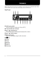
Page 7: ... r r r Control keys t t t t t Microphone jack Insert the microphone plug into this connector y y y y y key u u u u u A key i i i i i B key o o o o o C key 0 0 0 0 0 D key 1 1 1 1 1 CALL key q w t y u i o 1 0 e r Note Features listed in this section are available for both Trunking and Conventional modes Mode specific features can be found in their corresponding sections in this manual Front Panel ...

Page 8: ...ower on text or unit number appears for 2 seconds Press the IO switch again to switch the transceiver OFF Adjusting the Volume Press the volume keys to adjust the volume increases the volume and decreases it Rear Panel External speaker jack Power input connector Antenna connector ...

Page 9: ... activate its auxiliary function below Also press to scroll left while viewing stack entries 0 0 0 0 0 D key default setting None Press to activate its auxiliary function below Also press to scroll right while viewing stack entries 1 1 1 1 1 CALL key Press to call the displayed call address Programmable Auxiliary Functions The A B C and D keys as well as the external foot switch can be programmed ...

Page 10: ...re is new data in the stack displays call addresses the call duration timer data messages and the current operating status of the transceiver Searching for a Control Channel After switching the power ON press any key while the power on text or unit number is displayed to begin searching for a control channel Or wait for 2 seconds to allow the transceiver to start searching for a control channel au...

Page 11: ...w you selected the call address i ii and iii of step 1 When selecting a call address from memory or the stack press the CALL key or the microphone PTT switch if PTT to Initiate Call has been programmed to initiate the call iv of step 1 When using MPT1343 dialing press the microphone key to initiate the call Calling appears on the display 3 When the call is connected a timer appears on the display ...

Page 12: ...pressing the key END momentarily appears on the display before returning to the call address Status Calls Making a Status Call 1 Select a call address using one of the following two methods i Select a call address from memory Select your desired call address using the control keys if a call address has been stored in the transceiver memory ii Enter a call address using the microphone keypad Enter ...

Page 13: ...on received an invallid call NU You entered an invallid call address No Reply The called party has been called but they did not respond to the call Call Back The called party has set their transceiver to queue all incoming calls Sys Busy The system is currently busy Viewing the Stack 1 Press the Status Stack key default is the A key twice to enter the stack If there is no data in the stack appears...

Page 14: ...ars on the display before returning to the previously selected call address Diverting Third Party Calls 1 Enter control code 44 with the microphone keypad 2 Press the microphone key then enter the unit number of the transceiver which you want to divert the calls 3 Press the microphone key or the CALL key Calling appears on the display While your request is being processed Holding appears on the di...

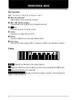
Page 15: ...to return to Trunking mode u u u u u A key Press to turn Scan ON or OFF i i i i i B key Press to add remove channels to from Scan 1 1 1 1 1 CALL key Press to turn the squelch OFF in order to monitor your selected channel Display displays the strength of received signals appears while you are monitoring a channel by pressing the CALL key appears while you are scanning displays channel numbers and t...

Page 16: ...ode the transceiver periodically searches for the network When it finds the network the transceiver automatically changes to Trunking mode An alert tone sounds to notify you when the operating mode changes Alert While in Conventional mode the transceiver periodically searches for the network When it finds the network an alert tone sounds Press the key to change the operating mode Conventional Mode...

Page 17: ... an adjustable time delay if the PTT switch is released and no further signal is received Only channels added to the scanning sequence will be scanned Channels which are added to the scanning sequence all have an add indicator in the left most segment of the main display To add a channel to the scanning sequence select the desired channel then press the B key appears on the display To remove a cha...

Page 18: ... 0 0 0 1 g n i l a i D t i g i D 5 n o i t c n u F g n i r t S l a i D s l l a c d r o w s s e r d d a e l g n i S l l a c X B A P 6 3 g n i r t s t s r i F 9 9 9 8 0 0 0 1 g n i r t s d n o c e S l o c o t o r p g n i s s e r d d a d e d n e t x E l l a c X B A P 8 r o 7 0 g n i r t s t s r i F 9 9 9 9 0 0 0 0 g n i r t s d n o c e S g n i l a i D t i g i D 6 n o i t c n u F g n i r t S l a i D l...

Page 19: ...r e t n I t e e l F 7 2 3 0 0 2 x i f e r P 9 8 0 2 l a u d i v i d n I 0 5 0 6 1 0 0 2 l l a c p u o r g t e e l f r e t n I x i f e r p r e t n I t e e l F 7 2 3 0 0 2 x i f e r P 9 9 0 9 p u o r G 0 5 0 6 1 0 0 2 l l a c N T S P 0 g n i r t s t s r i F 9 9 9 9 9 9 9 9 0 0 0 0 0 0 0 0 g n i r t s d n o c e S l o c o t o r p g n i s s e r d d a d e d n e t x e l l a c X B A P 8 r o 7 g n i r t s ...

Page 20: ...17 ...

Reviews: