TKR-740
16
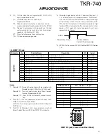
1.3. CONTROL I/ O jack
1
NC
No Connection
2
RXD2 (PC serial data to radio)
PC Read/Write, PC Tuning, Remote *1
I
RS-232C Level
3
TXD2 (PC serial data from radio)
PC Read/Write, PC Tuning, Remote *1
O
RS-232C Level
4
AUXI 1
Programmable Function input 1
*2
I
0 or 5V
5
AUXI 2
Programmable Function input 2
*2
I
0 or 5V
6
AUXI 3
Programmable Function input 3
*2
I
0 or 5V
7
DG (Digital Ground)
GND (for Digital ground only)
8
TD (TX Data input)
TX Signalling data input
*3
I
0.5Vpp
9
TA (TX Audio input)
TX Audio input
*3
I
140mVrms
10
RD (RX Data output)
RX Signalling data output
*3
O
80mVrms
11
RA (RX Audio output)
RX Audio output
*3
O
400mVrms
12
RXG (RX Ground)
GND (for RA, RD ground only)
13
SPM (Speaker Mute)
Mute input;
“
Mute: Low
”
I
0 or 5V
14
NC
No Connection
15
EXT MON (Monitor SW)
External Monitor input;
“
Active: Low
”
*5
I
0 or 5V
16
EXT PTT (Same as Test SW)
External PTT input
“
ON: 0V OFF: 5V
”
*3
I
0 or 5V
17
SC (Squelch Control)
Squelch status output;
“
Busy: Low
”
O
0 or 5V
18
NC
No Connection
19
TXG (TX Ground)
GND (for TA,TD ground only)
*3
20
AUXO 1
Programmable Function output 1
*4
O
0 or 5V
21
AUXO 2
Programmable Function output 2
*4
O
0 or 5V
22
AUXO 3
Programmable Function output 3
*4
O
0 or 5V
23
AUXO 4
Programmable Function output 4
*4
O
0 or 5V
24
AUXO 5
Programmable Function output 5
*4
O
0 or 5V
25
AUXO 6
Programmable Function output 6
*4
O
0 or 5V
Connector
No.
Terminal Name
Description
I/ O
Level
CO
N
T
RO
L
I/
O
CONTROL I/ O (25pin D-SUB) jack
(View ed from Back Panel)
Notes:
*1Serial data communications with a PC can be done through
either front panel 8-pin modular microphone jack or the rear
panel 25-pin D-SUB interface connector. Firmware can only
be written through the 8-pin modular microphone jack.
M ode
8pin M odular
25pin D-sub
FPU Read/Write
Yes
Yes
FPU Tuning mode
Yes
Yes
Firmware programming
Yes
No
Serial Remote
No
Yes
Real time Monitor
No
Yes
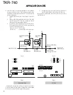
*2All AUX I terminals (Section 1.3, 1.4), including any AUX I/O
programmed as
“
AUX Input
”
with the KGP-47D are Active-
Low logic.
Serial Data transmission method
●
Full duplex communication
●
Asynchronous system (start-stop asynchronous)
●
Non-parity check
●
Start bit: 1bit, Stop bit: 2bit
●
Data: 8bit, LSB output
●
Baud rate: 9600bps
●
Hardware flow control line not used
APPLICATION NOTE
13 12 11 10 9
8
7
6
5
4
3
2
1
25 24 23 22 21 20 19 18 17 16 15 14
Summary of Contents for TKR-740
Page 97: ...TKR 740 TKR 740 BLOCKDIAGRAM 121 122 ...
Page 99: ...TKR 740 TKR 740 INTERCONNECTION DIAGRAM 125 126 ...
Page 101: ...MEMO 129 ...

