TKR-740
21
APPLICATION NOTE
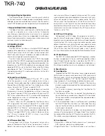
2.2. Intercom Function
The Intercom function allows two communications between
a dispatcher at a remote console and the TKR-740 unit at a
site via the remote termination unit-to-console audio link. This
function operates in repeater or base station mode.
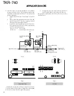
1) Connect the 12-pin Remote I/O Connector on TKR-740 to
the interface port on Remote Termination unit with a cable.
2) Select PTT Priority if desired: Local Mic PTT, Ext. PTT (ext.
controller), Remote PTT (remote termination unit), Repeat
PTT (TKR-740 internal controller repeat PTT). This allows
for example the Remote PTT can take precedent over the
Ext. PTT and front panel Local Mic PTT.
<Edit>
➔
<Optional features>
➔
<PTT Priority...>
3) Select the audio routing during Intercom operation (Remote,
Local or Remote/Local)
<Edit>
➔
<Optional features>
➔
“
Intercom Remote/Local
”
Remote: Remote TA, transmit audio out from the
remote term. unit will be heard in the front panel
speaker when the Remote PTT is active even if
receiver audio is present. Audio from the Remote
TA port will also be transmitted over the air (see
5; TX Disable).
Local:
Front panel Local Mic audio will be routed to the
Remote RA port (audio input to the remote term.
unit) even if receiver audio is present. Audio from
the Local Mic will be transmitted over the air (see
5; TX Disable).
Remote/Local:
Remote TA, transmit audio out from the
termination unit will be heard in the front panel
speaker. Front panel mic audio will be routed to
the Remote RA audio input to the remote
termination unit, even if receiver audio is present.
All audio will be transmitted over the air (see 5
TX Disable). Transmit Audio priority is dependent
on the PTT Priority setting.
4) Program a front panel PF key or AUX Input to set Intercom
ON/OFF.
<Edit>
➔
<Key assignment>
➔
“
Intercom ON/OFF
”
<Edit>
➔
<Optional features>
➔
<AUX I/O Ports...>
➔
<AUX Input Functions (12-pin & 25-pin)... >
➔
“
Intercom
On/Off
”
5) To inhibit Intercom audio from being transmitted over the
air, program a front PF key and/or AUX Input to disable
transmit during Intercom.
To use the Intercom with Local Mic PTT without keying the
transmitter, enable the Local TX Disable function at PF key
or AUX Input. This must be manually activated by the Local
Mic user.
<Edit>
➔
<Key assignment>
➔
“
TX Disable/Enable
”
To use the Intercom with Remote PTT without keying the
transmitter, enable the Remote TX Disable function at PF
key or AUX Input. If a PF key is programmed the Local Mic
user must activate this during Intercom operation. If an AUX
Input is programmed, a
“
function
”
or
“
auxiliary
”
function
switch on the remote console must be used to activate the
AUX Input (prog. for Remote TX Disable) during Intercom
operation.
<Edit>
➔
<Optional features>
➔
<AUX I/O Ports...>
➔
<AUX Input Functions (12-pin & 25-pin)...>
➔
“
TX
Disable/Enable
”
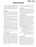
2.3. Setting for Voting system
1) The Voting Tone is output from the RA port of the 25-pin D-
sub and interfaced with the audio link of the systems voting
Comparator unit. This link may be a dedicated telco line or
an RF link such as a point-to-point microwave or conventional
analog FM link. (Note: The voting tone will also be output
through the Remote RA audio port. If Intercom operation is
activated then Local Mic audio will be outputted. Do not
use the Remote RA port for the voting output when Intercom
operate).
2) Program the voting tone frequency by pressing PF2 or space
bar.
<Edit>
➔
<Optional features>
➔
<Voting tone>
➔
“
1950
”
Note: Set to
“
Disable
”
for non-voter system use.
3) A front panel key can be programmed for a Voting Tone On/
Off function for service and test purposes.
<Edit>
➔
<Key assignment>
➔
<PF key >
➔
“
Voting Tone
ON/OFF
”
2.4. Digital Paging systems
The TKR-740 can be used as a continuous-duty paging
transmitter. It has a direct carrier frequency shift input for bi-
level type paging protocols such as POCSAG (note this is not
for quad-level formats such as Motorola Flex).
1. Program the Digital Paging Input as
“
Enable
”
:
<Edit>
➔
<Optional features>
➔
<Digital Paging
Input>
➔
“
Enable
”
When this function is set to
“
Enable
”
, AUX Input 2 is
automatically assigned as the
“
Digital Pager PTT
”
and AUX
Input 3 is automatically assigned
“
Digital Pager Data
”
.
Digital Pager Data Input level (AUX Input 3):
+5.30V > High > +4.0V
-0.30V < Low < +1.00V
Digital Pager PTT Input (AUX Input 2): Active Low
Baud Rate: Less than 2400 bps
Frequency Shift Polarity:
High: -4.0 kHz ±0.5 kHz shift
Low: +4.0 kHz ±0.5 kHz shift
Adjust the Digital Pager Deviation at 102 digit in FPU for
4.0kHz shift.(0 digit; 0 kHz 255 digit; 8.4kHz)
Caution ;Pin5(AUX Input 2) on the 25-pin D-Sub connector
corresponds to a RS-232C CTS. when Digital Paging Input is
“
Enable
”
and the 25-pin D-Sub on TKR-740 is connected to
the serial port on PC with a 25-pin D-Sub straight cable, note
that TKR-740 is likely to transmit.
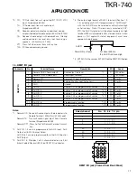
3. Internal I/ O Terminal Description
The TKR-740 has internal connection terminals for adding
internal option boards such as voice encryption /scramblers
boards, ANI encoders and tone encoders (two-tone, burst, 5-
6 tone, etc.).
Summary of Contents for TKR-740
Page 97: ...TKR 740 TKR 740 BLOCKDIAGRAM 121 122 ...
Page 99: ...TKR 740 TKR 740 INTERCONNECTION DIAGRAM 125 126 ...
Page 101: ...MEMO 129 ...


