TKR-740
29
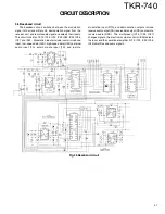
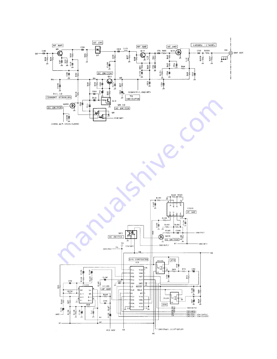
2.6 M odulation level adjustment circuit
The level adjustment circuit adjusts the modulation signal
level to provide the required level of modulation and adjusts
the transmitter output pow er. This circuit consists of IC105,
IC3, IC100, IC102, IC203, Q208, and Q21. IC3 is an electronic
volum e cont rol IC. The signalling f requency change
adjustment, signalling modulation balance adjustment, digital
pager modulation w aveform balance adjustment, maximum
AF Dev. change, and t he ref erence volt age set t ing f or
transmitter pow er adjustment are performed according to data
from the CPU using the FPU. IC105 is a modulation signal
summing amplifier (A/2) and a signalling signal amplitude fine-
adjustment amplifier (B/2). IC102 is a splatter filter for digital
pager modulation and has a tw o-stage Butterw orth filter w ith
a cutoff frequency of 1.9kHz. IC203 is a DC amplifier that
amplifies the transmitter pow er reference voltage generated
by IC3. Q21 outputs 5 V to the final unit as an H/L signal w hen
the transmitter pow er mode is “ LOW” and outputs 0 V w hen
the transmitter pow er mode is “ HIGH” .
Fig.6 M odulation level adjustment circuit
CIRCUIT DESCRIPTION
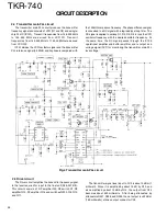
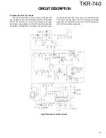
Fig.5 Driver circuit
Summary of Contents for TKR-740
Page 97: ...TKR 740 TKR 740 BLOCKDIAGRAM 121 122 ...
Page 99: ...TKR 740 TKR 740 INTERCONNECTION DIAGRAM 125 126 ...
Page 101: ...MEMO 129 ...


