TKR-740
30
CIRCUIT DESCRIPTION
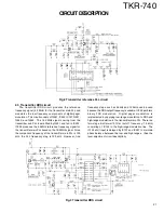
2.7 Other circuits
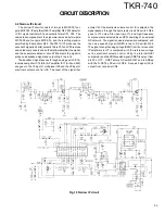
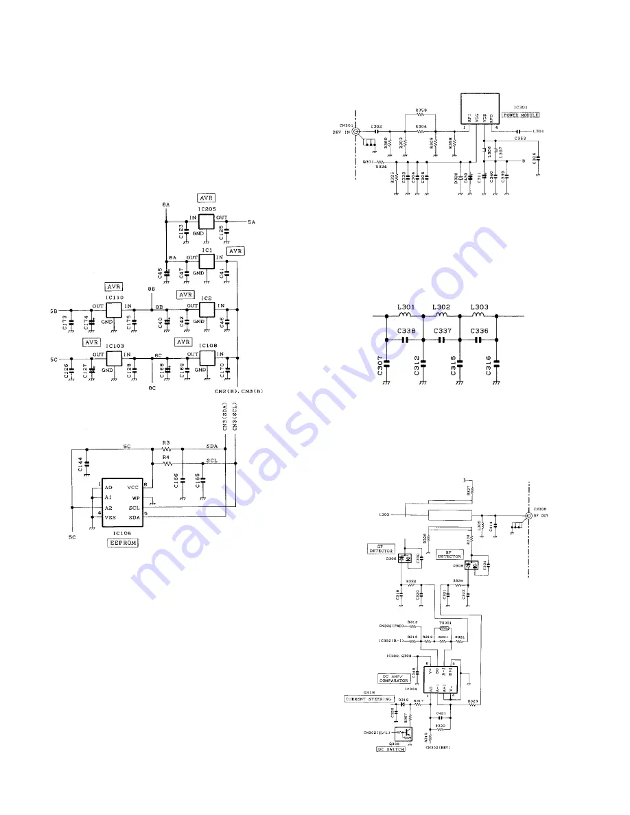
In addit ion, IC106 is an EEPROM . The t ransm it t er
adjustment data adjusted for each unit is w ritten into the
EEPROM . If the unit is installed in another set, it is not
necessary to adjust it again from the beginning, but only fine-
adjustment is necessary for each unit.
IC1, IC2, IC103, IC108, IC205, and IC110 are three-pin AVR
ICs. Each circuit contains its ow n pow er regulator IC to
maintain isolation betw een circuits.
Fig.7 Other circuits
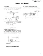
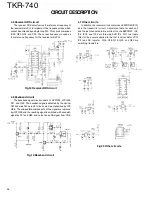
Fig.9 Harmonic filter circuit
3.2 Harmonic filter circuit
The harmonic filter circuit uses a three-stage “ pi” type
Chebyshev type LPF consisting of L301, L302, L303, C307,
C312, C315,C316, C336, C337, and C338. This circuit removes
harmonics from the transmitter output and sends the filtered
signal to the forw ard/reflected pow er detector circuit.
3. Final Unit
The RF final amplifier unit (X56-307 B/3) amplifies transmitter
pow er to a specified level. This unit consists of the follow ing
circuits: (1) Transmitter pow er module, (2) harmonic filter
circuit, (3) forw ard/reflected pow er detector circuit, (4) APC
circuit, (5) high temperature detector circuit, (6) common mode
spurious filter circuit.
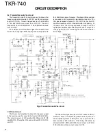
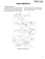
3.1 Transmitter pow er module
The pow er m odule IC301 uses a pow er m odule
RA30H1317M to improve its efficiency. The driver output of
the transmitter unit passes through an attenuator and enters
pow er module IC301 on its pin 1. Pow er module IC301
amplifies the RF pow er according to the voltage at the
amplification control pin 2 (VGG) and outputs it on pin (RFO).
Fig.8 Transmitter pow er module
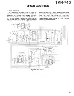
3.3 Forw ard/ reflected pow er detector circuit
The forw ard/reflected pow er detector circuit consists of a
CM coupling type detection circuit formed by a strip line and a
DC amplifier IC303 (A/2, B/2). The transmitter pow er w hich
passes through the strip line is output from CN308.
Fig.10 Forw ard/ reflected pow er detector circuit
Summary of Contents for TKR-740
Page 97: ...TKR 740 TKR 740 BLOCKDIAGRAM 121 122 ...
Page 99: ...TKR 740 TKR 740 INTERCONNECTION DIAGRAM 125 126 ...
Page 101: ...MEMO 129 ...


