TKR-740
72
ADJUSTMENT
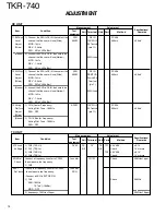
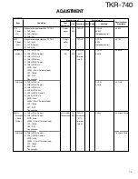
RX UNIT
1. Setting
1) VOL : OFF
2) 13.2V External pow er supply
3) POWER : ON
2. RX Lock
1) CH6 (RX B Hi)
DVM
RX
CV1
RX
TC2 4.5V ADJ
± 0.1V
Voltage
2) CH4 (RX B Lo)
Check
1V or more
3) CH3 (RX A Hi)
TC1 4.5V ADJ
± 0.1V
4) CH1 (RX A Lo)
Check
1V or more
3. BPF
Connect the TG to RX IN, then connect
TG Spectrum
RX IN
L3
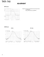
Center the frequency
Refer to page 80
Adjust
CN2 to the spectrum analyzer input.
Analyzer
CN2
L16 you are using, then
adjust it to look like
the w ave on page 80.
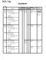
4. M CF
Connect the TG to CN3, then connect
CN3
L31 Adjust it to look like
Refer to page 80
Adjust
CN4 to the spectrum analyzer input.
CN4
L27 the w ave on page 80.
(Wide)
1) CH4
L38
L40
L43
(Narrow ) Connect the TG to CN3, then connect CN5
CN3
L32 Adjust it to look like
Refer to page 80
to the spectrum analyzer input.
CN5
L28 the w ave on page 80.
1) CH10
L39
L41
L44
5. Discriminator
Connect the SSG to RX IN
SSG
TEST/SPKR
L52 Adjust for maximum
Adjust
1) CH4
AFVM
SPO Terminal
(Wide)
M OD: 1kHz
(pin 12)
DEV : 2.4kHz
SSG : 501
µ
V (–53dBm)
AF : 0.45V/4
Ω
(Narrow ) 1) CH10
L53
M OD: 1kHz
DEV 1.5kHz
SSG : 501
µ
V (–53dBm)
AF : 0.45V/4
Ω
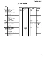
6. Sensitivity 1) Connect the SSG to RX IN, then select the
SSG
RX IN
Check
20dB SINAD
Check
channel that the user w ill use (Wide)
Audio,
TEST/SPKR
or more
(Wide)
M OD: 1kHz
Analyzer
SPO Terminal
DEV : 2.4kHz
(pin 12)
SSG : 0.707
µ
V (–110dBm)
AF : 0.45V/4
Ω
filter : CCITT
(Narrow ) 1) Connect the SSG to RX IN, then select the
channel that the user w ill use (Narrow )
M OD: 1kHz
DEV : 1.5kHz
SSG : 0.707
µ
V (–110dBm)
AF : 0.45V/4
Ω
filter : CCITT
Item
Condition
M easurement
Adjustment
Specifications/
Test
Unit Terminal Unit Parts
M ethod
Remarks
equipment
Summary of Contents for TKR-740
Page 97: ...TKR 740 TKR 740 BLOCKDIAGRAM 121 122 ...
Page 99: ...TKR 740 TKR 740 INTERCONNECTION DIAGRAM 125 126 ...
Page 101: ...MEMO 129 ...


