TKR-D710
7
1. External Speaker (KES-5)
The TKR-D710 has a built-in speaker (5W/8
), and the
external speaker output from the TEST/SPKR connector (15-
pin) on the rear of the radio is 4W/4
. Use external speaker
KES-5.
1-1. Connection for the KES-5 with the TKR-D710
■
When taking the AF output from the TEST/SPKR
connector (15-pin) on the rear of the radio
The following tools are required for changing the connec-
tor.
• Extracting tool
The following extracting tool is recommended:
Molex Inc. Order No.: 11-03-0002 (W05-0878-00)
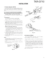
1. Remove the connector with jumper from the external
speaker connector on the rear panel of the radio. (Fig.1-1)
Note:
Save the jumper, which is required when the radio
is used without the external speaker.
2. Remove the terminals with the jumper from the connec-
tor housing holes number 9 and 12 using the extracting
tool.
Removing the jumper lead (Fig. 1-2)
1)
Insert the extracting tool (11-03-0002) into the connec-
tor while pushing the jumper lead in the direction of (a).
2)
Push the extracting tool in to collapse the barbs of the
crimp terminal.
3)
Pull out the lead while continuing to push the extract-
ing tool in the direction (b).
3. Reinsert the terminal with the black and white stripe lead
into hole number 12, and the terminal with the black lead
into hole number 6. (Fig. 1-3)
4. Attach the connector to the external speaker connector
on the radio.
Note:
Relationship between the TEST/SPKR connector (15-pin)
connection and speaker output:
• When pins 9 and 12 are shorted: The built-in speaker is
used.
• When pins 9 and 12 are open and output is from pins 6
and 12: KES-5 is used.
Square-type plug
(E31-3228-05)
Accessory
Fig. 1-1
INSTALLATION
Jumper lead
Crimp termial
Crimp termial
Barbs
Extracting tool
(11-03-0002)
(a)
(b)
Fig. 1-2
Crimp terminal
(E23-0613-05)
12
15
13
1
3
6
Black/White lead
Black lead
Fig. 1-3
2. Accessory Cabinet
You can install optional accessories, such as a DC power
supply or duplexers, in the accessory cabinet.
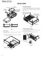
1. Place the optional accessory in the cabinet as shown be-
low.
2. If necessary, attach cushions (G13-1801-04 and/or G13-
1802-04) to the top plate (J21-8559-04) in order to adjust
the space between the cabinet and the top plate. Then,
insert the 3 tabs of the plate into the slots in the side of
the cabinet. High, middle, or low positions are available.
To affi x the plate, inset and tighten the 2 screws on the
other side of the plate.
You can also fl ip the top plate upside-down to adjust the
height of the cabinet space.
Summary of Contents for TKR-D710
Page 71: ...TKR D710 71 MEMO ...
Page 108: ...TKR D710 108 MEMO ...
Page 110: ...Printed in Japan No RQ148 Communications Systems Business Operation ...


