TM-481A
7
■
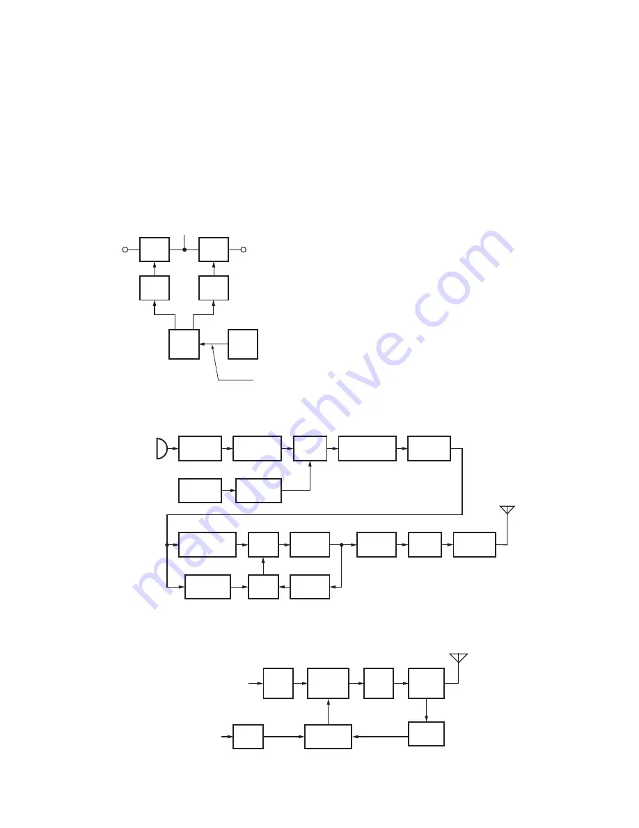
Unlock Circuit
During reception, the 8RC signal goes high, the 8TC
signal goes low, and Q708 turns on. Q710 turns on and a
voltage is applied to 8R. During transmission, the 8RC sig-
nal goes low, the 8TC signal goes high and Q70
9
turns on.
Q711 turns on and a voltage is applied to 8T.
The MCU monitors the PLL IC (IC1) LD signal directly.
When the PLL is unlocked during transmission, the PLL LD
signal goes low. The MCU detects this signal and makes the
8TC signal low. When the 8TC signal goes low, no voltage
is applied to 8T, and no signal is transmitted. (See Fig. 7.)
IC707
MCU
Q708
SW
Q710
SW
IC1
PLL
Q709
SW
Q711
SW
LD
8RC
8C
8R
8T
8TC
PLL lock
: LD “H”
Fig. 7 Unlock circuit
Transmitter System
■
Outline
The transmitter circuit produces and amplifi es the desired
frequency directly. It FM-modulates the carrier signal by
means of a varicap diode.
■
Power Amplifi er Circuit
The transmit output signal from the VCO passes through
the transmission/reception selection diode (D
9
, D10) and is
amplifi ed by Q303. The amplifi ed signal goes to the power
module (IC302) through a low-pass fi lter. The low-pass fi lter
removes unwanted high-frequency harmonic components,
and the resulting signal is transmitted through the antenna
terminal. (See Fig. 8.)
■
APC Circuit
The automatic transmission power control (APC) circuit
detects part of a fi nal amplifi er output with a diode (D313,
D314) and applies a voltage to IC303. IC303 compares the
APC control voltage (PC) generated by the D/A converter
(IC705) and DC amplifi er (IC706) with the detection output
voltage. IC303 generates the voltage to control the Vgg of
IC302 and stabilizes the transmission output.
The APC circuit is configured to protect over current of
IC302 due to fl uctuations of the load at the antenna end and
to stabilize transmission output at voltage and temperature
variations. (See Fig.
9
.)
Fig. 8 Transmitter system
Fig. 9 APC circuit
Q10
RF AMP
Q303
ANT
DRIVE
AMP
IC302
POWER
MODULE
IC705
Q6
D/A
CONVERTER
D/A
CONVERTER
X1
TCXO
16.8MHz
VCO
IC1
PLL
Q9
BUFFER
Q3
RF AMP
IC706
BUFFER
IC101
IC705
MIC KEY
INPUT
MCU
IC706
SUM
AMP
IC704
IC703
MIC
MIC/IDC
SPLATTER
FILTER
DRIVE
AMP
Q303
POWER
MODULE
IC302
DC
AMP
IC706
ANT
SW
D306,D307
D309,D311
LPF
ANT
POWER
DET
D313,D314
IC303
APC
CONTROL
D9
IC705
(PC/TVO)
(PC)
CIRCUIT DESCRIPTION


