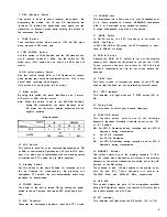
Use of SQUELCH control
This control is used to eliminate noise when Signal is ab-
sent. Turn the control slowly until noise disappears. When
the control is properly adjusted, only the receive Signal is
heard from the speaker. This control is also used according
to the strength of input Signal during mobile Operation.
Transmission
Notes:
1. B e f o r e t r a n s m i t t i n g , perform a l l t h e n e c e s s a r y pro-
cedures for Optimum reception. Make sure that the fre-
quency you have selected does not interfere with other
stations.
2. Check to make sure that the antenna connected is of the
proper type. Use of an improper antenna will result not
only in insufficient power but also in TV1 and BC1 .
D
O
not attempt to operate the transceiver without con-
n e c t i n g a n t e n n a a s i t w i l l Cause d a r n a g e t o t h e
transceiver.
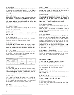
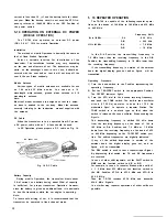
Fig. 10 Transmission
Set the controls referring to Fig. 9. For transmission, use
the following procedure:
1. Set the MODE switch to FM and the STANDBY switch
to SEND (when the PTT switch is pressed, Signal is
transmitted at the REC Position of the standby switch).
Check to see that the RF meter is working and the ON
AIR indicator is lit. Set the STANDBY switch to REC.
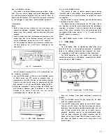
2. Adjust the microphone gain by turning the FM MIC con-
trol. Normally, Optimum gain is obtained in the Center
Position o f t h e k n o b . I f r e q u i r e d , t u r n t h e c o n t r o l
counterclockwise to reduce the gain.
C e n t e r Dosition
Fig. 11 MIC GAIN Adjustment
Use of LOW POWER Switch
This switch is used to reduce transmit power during
Operation with a local Station, thus preventing interference
to other stations. lt is also effective to reduce the power
consumption.
Set the switch to the up Position and the transmit power
is reduced to about 1 Watt.
The transmit power is indicated on the RF meter. Since
the indication on the RF meter depends on the installation
condition of antenna, it will not indicate the exact output
power. If the meter indicates “8” at the rated power, then
the reading of the meter will be “1” or “2” when the LOW
POWER switch is turned on.
Note:
The LOW POWER switch is used in FM mode only.
5-3.
SSB Mode
Reception
On VHF bands, USB is traditionally more often used
than LSB. As far as the operating technique is concerned,
there is no differente between two. Generally, the “zero-
in” technique in SSB mode required a little experience.
For SSB Operation, set the knobs and switches as
described in section on “FM Mode”, except that the MODE
switch should in USB Position.
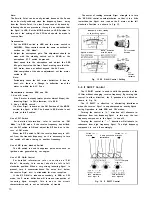
Fig. 12 Transmission in SSB Mode
After the settings have been completed, proceed as
follows:
1. Turn the POWER switch ON and adjust the AF GAIN
knob for suitable loudness.
2. Turn the VFO tuning knob slowly to receive SSB Signal.
First set the VFO knob a few kHz lower than the receive
frequency (turn the knob counterclockwise) and you will
hear a high pitched tone such as is heard from a
magnetic recording tape set in the fast-forward mode.
Turn the knob clockwise for higher frequency and the
Sound will become clearer. Set the knob in such a posi-
tion where the Sound is heard most clearly (this is the
Zero-in Point).
12

