background image

Installation / Installation / Instalación

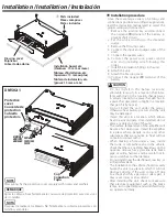
Installation procedure

Since there are large variety of settings and 

connections possible according to applications, 

read the instruction manual well to select the 

proper setting and connection.

1. Remove the ignition key and disconnect 

the negative

terminal of the battery to 

prevent short circuits. 

2. Set the unit according to the intended 

usage.

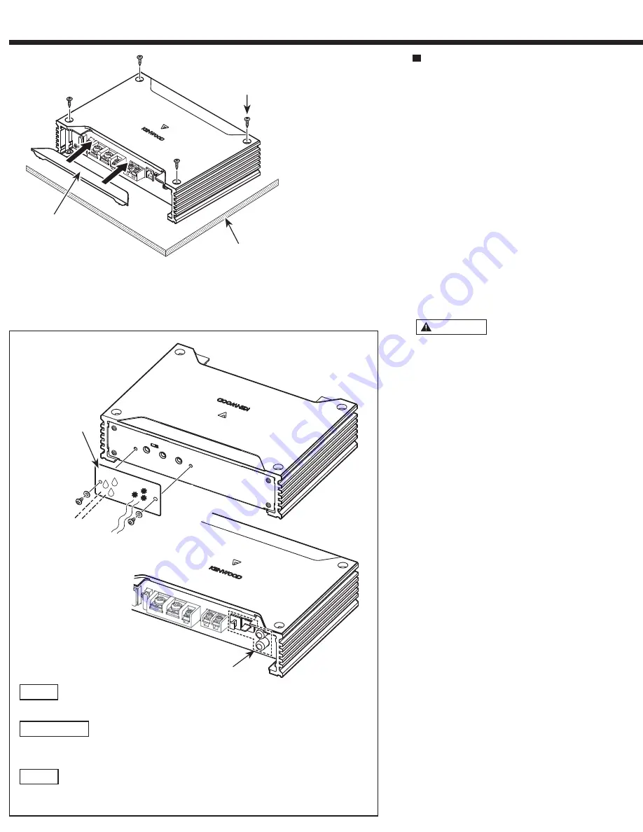
3. Remove the Dressing cover.

4. Connect the input and output wires of the 

units.

5. Connect the speaker wires.

6. Connect the power wire, power control 

wire and grounding wire following this 

order.

7. Install the installation fittings in the unit.

8. Attach the unit.

9. Attach the Dressing cover.

10. Connect the negative

terminal of the 

battery.

 CAUTION

• Do not install in the below locations;

(Unstable location, In a location that inter-

feres with driving, In a location that gets wet, 

In a dusty location, In a place that gets hot, In 

a place that gets direct sunlight, In a location 

that gets hit by hot air)

• Do not install the unit under the carpet. 

Otherwise heat build-up occurs and the unit 

may be damaged.

• Install this unit in a location which allows 

heat to easily dissipate. Once installed, do not 

place any object on top of the unit.

• The surface temperature of the amplifier will 

become hot during use. Install the amplifier 

in a place where people, resins, and other 

substances that are sensitive to heat will not 

come into contact with it.

• When making a hole under a seat, inside

the trunk, or somewhere else in the vehicle, 

check that there is nothing hazardous on the 

opposite side such as a gasoline tank, brake 

pipe, or wiring harness, and be careful not to 

cause scratches or other damage.

• Do not install near the dashboard, rear tray, or 

air bag safety parts.

• The installation to the vehicle should securely 

fasten the unit to a place in which it will not 

obstruct driving. If the unit comes off due 

to a shock and hits a person or safety part, it 

may cause injury or an accident.

• After installing the unit, check to make sure 

that electrical equipment such as the brake 

lamps, turn signal lamps and windshield wip-

ers operate normally.

DUST
POUSSIÈRE
POLVO

MOISTURE
HUMIDITÉ
HUMEDAD

Installation board, etc. 
(thickness: 15 mm or more)
Tableau d’installation, etc. 
(épaisseur: 15 mm ou plus)
Tablero de instalación, etc. 
(grosor: 15 mm o más)

Parts included
Pièces comprises
Partes incluidas

Dressing cover
Enjoliveur
Cubierta de adorno

XM502-1

Protective 

cover
Couvercle de 

protection
Cubierta 

protectora

ra

NOTE

After wiring, fix the protective cover securely with screws and washers.

REMARQUE

Après le câblage, fixez fermement le couvercle de protection avec des vis et 

des rondelles.

NOTA

Después de realizar el cableado, fije firmemente la cubierta protectora con 

tornillos y arandelas.

Cap

Capuchon

Tapa

Summary of Contents for X502-1

Page 1: ...anty card and in the space provided below Refer to the model and serial numbers whenever you call upon your Kenwood dealer for information or service on the product Model X502 1 XM502 1 Serial number US Residence Only Register Online Register your Kenwood product at www kenwood com usa B5A 3481 10 01 KN WN 2021 JVCKENWOOD Corporation 213 mm 8 3 8 149 mm 5 7 8 53 mm 2 1 16 Accessories Accessoires A...

Page 2: ...t turning the engine ON it depletes the battery Use it after starting the engine Protection function The protection function is activated in the following situations This unit is equipped with a protection function for protecting this unit and your speakers from various acci dents or problems that can occur When the protection function is triggered the power indicator goes off and the amplifier st...

Page 3: ...he amplifier in a place where people resins and other substances that are sensitive to heat will not come into contact with it When making a hole under a seat inside the trunk or somewhere else in the vehicle check that there is nothing hazardous on the opposite side such as a gasoline tank brake pipe or wiring harness and be careful not to cause scratches or other damage Do not install near the d...

Page 4: ... immédiatement l appareil hors tension et vérifier tous les raccordements Veiller à mettre l appareil hors ten sion avant de changer la position des commutateurs Si le fusible saute vérifier si les câbles ne sont pas court circuités et remplacer le fusible par un autre fusible de même capacité nominale Vérifier qu aucun câble ou connecteur non raccordé ne touche la carrosserie de la voiture Ne pas...

Page 5: ...rque podría producirse una avería Connections Raccordements Conexiones RCA INPUT connection Raccordement RCA INPUT Conexión RCA INPUT Speaker level input connections Raccordement au niveau haut parleur Conexión para entrada de altavoz AFTERMARKET HEADUNIT L R FRONT L R L R FACTORYINSTALLED HEADUNIT RCA cable Câble RCA Cable RCA Power control wire Câble de commande de l alimentation Cable de contro...

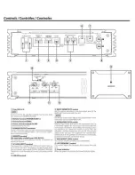
Page 6: ...ed on and off as the unit detects input signal SIGNAL SENSING TURN ON Therefore it is not necessary to connect the power control wire LINE IN terminal 12 INPUT SENSITIVITY control Set this control according to the pre output level of the HEAD UNIT connected with this unit INOTE I For the pre output level refer to the Specifications in the instruction manual of the HEAD UNIT INFRASONIC FILTER switc...

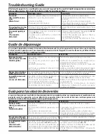
Page 7: ...veau de sortie trop faible ou trop fort La commande de réglage de la sensibilité d en trée n est pas amenée sur la bonne position Faire le réglage correctement en se reportant aux indications données en Contrôles La qualité sonore est mauvaise Le son est distordu Les câbles de haut parleur ont été raccor dés en inversant la polarité Un câble de haut parleur est pincé par une vis dans le châssis de...

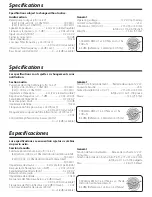
Page 8: ...0 2 V 5 0 V Relación señal a ruido 100 dB Impedancia de entrada 10 kΩ Frecuencia del filtro pasa bajos 24 dB octava 50 Hz 200 Hz variable Frecuencia del filtro infrasónico 24 dB octava 25 Hz Control acentuador de graves 40 Hz 0 18 dB variable General Tensión de funcionamiento Batería de coche de 12 V CC Consumo 25 A Tamaño de instalación Anch Alt Prof 213 53 149 mm 8 3 8 2 1 16 5 7 8 pulgada Peso ...

Page 9: ...de la vida útil aplicable a los países que hayan adoptado sistemas independientes de recogida de residuos Los productos con el símbolo de un contenedor con ruedas tachado no podrán ser desechados como residuos domésticos Los equipos eléctricos y electrónicos al final de la vida útil deberán ser reciclados en instalaciones que puedan dar el tratamiento adecuado a estos productos y a sus subproducto...

Page 10: ...dio or television reception which can be determined by turning the equipment off and on the user is encouraged to try to correct the interference by one or more of the following measures Reorient or relocate the receiving antenna Increase the separation between the equipment and receiver Connect the equipment into an outlet on a circuit different from that to which the receiver is connected Consul...

Reviews: